 Vespa GTS Super 300 ie - Service manual > Plastic roller
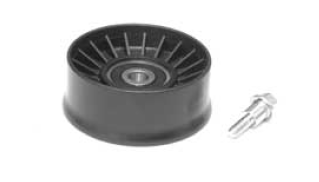
- Check that the roller does not show signs of wear and that it turns freely.
- Remove the special clamping screws as indicated in the photograph
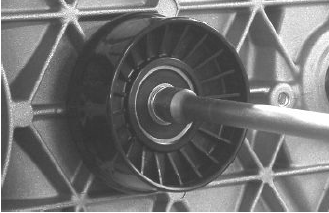
- Check the outer diameter of the roller does not have defects that could jeopardise belt functioning
- For refitting, place the roller with the belt containment edge on the engine crankcase side
- Tighten the wrench to the prescribed torque.
Locking torques (N*m)
Anti-flapping roller 12 - 16
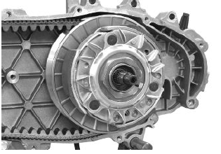
Removing the driven pulley
- Remove the clutch housing and the driven pulley assembly.
N.B.
THE UNIT CAN ALSO BE REMOVED WITH THE DRIVING PULLEY MOUNTED.
Inspecting the clutch drum
- Check that the clutch bell is not worn or damaged.
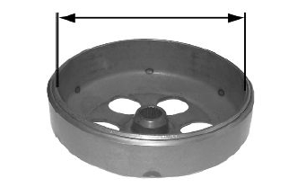
- Measure the clutch bell inside diameter.
Characteristic
Max. value clutch housing
Max. value: Ø 134.5 mm
clutch housing standard value
Standard value: Ø 134 - 134.2 mm
Checking the bell working surface eccentricity
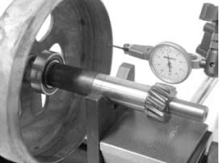
- Install the bell on a driven pulley shaft using 2 bearings (inside diameter: 15 and 17 mm).
- Lock with the original spacer and nut.
- Place the bell/shaft unit on the support to check the crankshaft alignment.
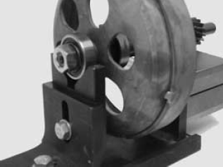
- Using a feeler dial gauge and the magnetic base, measure the bell eccentricity.
- Repeat the measurement in 3 positions (Central, internal, external).
- If faults are found, replace the bell.
Specific tooling
020074Y Support base for checking crankshaft alignment
020335Y Magnetic mounting for dial gauge
Characteristic
clutch housing inspection: Limit eccentricity.
Admissible limit eccentricity: 0.15 mm
See also:
 Vespa GTS Super 300 ie - Service manual > Removing the clutch
Fit the driven pulley spring compressor specific tool with medium length pins screwed in position "C" on the tool internal side. Introduce the adapter ring 11 with the chamfering facing the inside of the tool. Fit the driven pulley unit on the tool with the insertion of the 3 pins in the ventilation holes in the mass holder support. Make sure that the clutch is perfectly inserted into the adapter ring before proceeding to loosen/tighten the clutch nut. Use the special 46x55 wrench component 9 to remove the nut fixing the clutch in place. Dismantle the driven pulley components (Clutch and spring with its plastic holder)


