 Suzuki Burgman 400 - Service manual > Precautions
Precautions for Engine Mechanical
Refer to "General Precautions".
Schematic and Routing Diagram
Camshaft and Sprocket Assembly Diagram
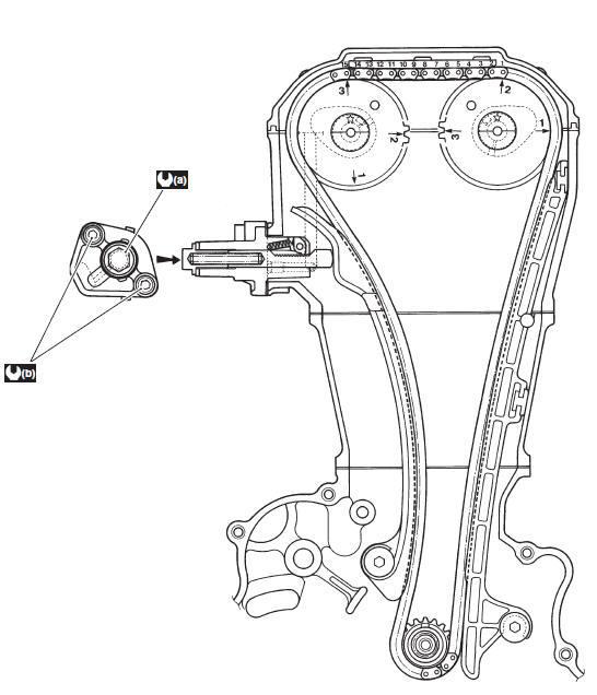
- 23 N*m (2.3 kgf-m, 16.5 lb-ft)
- 10 N*m (1.0 kgf-m, 7.0 lb-ft)
Throttle Cable Routing Diagram
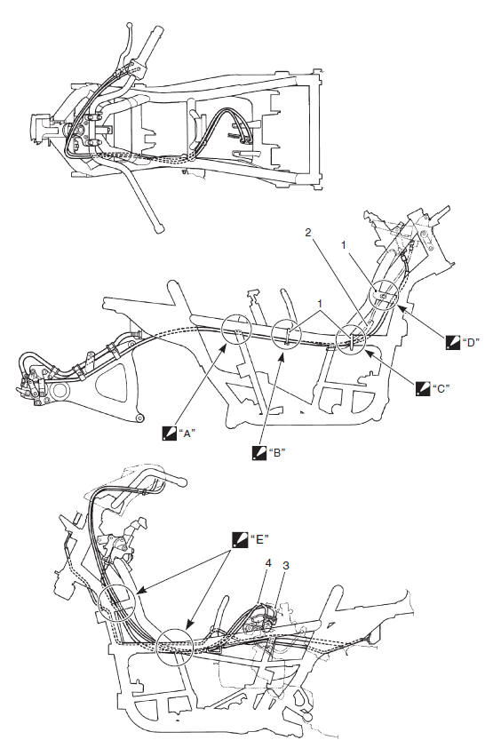
- Clamp
- Wire harness
- Throttle cable No. 1
- Throttle cable No. 2
- Pass the throttle cables through inside of the frame.
- Pass the throttle cables through under and inside of the frame.
Bind the brake-lock cable, starter motor lead wire and seat-lock cable together.
- Pass the throttle cables through inside of the frame.
Bind the parking brake cable starter motor lead wire and seat-lock cable together.
- Pass the throttle cables through inside of the frame.
- Pass the throttle cables through inside of the frames.
Diagnostic Information and Procedures
Compression Pressure Check
The compression pressure reading of the cylinder is a good indicator of its internal condition.
The decision to overhaul the cylinder is often based on the results of a compression test. Periodic maintenance records kept at your dealership should include compression readings for each maintenance service.
NOTE
- Before checking the engine for compression pressure, make sure that the cylinder head bolts are tightened to the specified torque and the valves are properly adjusted.
- Make sure that the battery is in fully-charged condition.
1) Warm up the engine.
2) Remove the spark plug. Refer to "Spark Plug Removal and Installation".
3) Install the compression gauge and adaptor in the spark plug hole. Make sure that the connection is tight.
Special tool
(A): 09915-64512 (Compression gauge)
(B): 09913-10750 (Compression gauge adapter)
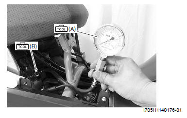
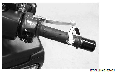
4) Keep the throttle grip in the fully-opened position.
5) Press the starter button and crank the engine for a few seconds. Record the maximum gauge reading as the cylinder compression.
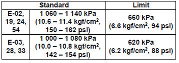
Compression pressure specification
Low compression pressure can indicate any of the following conditions:
- Excessively worn cylinder wall
- Worn piston or piston rings
- Piston rings stuck in grooves
- Poor valve seating
- Ruptured or otherwise defective cylinder head gasket
6) After checking the compression pressure, reinstall the removed parts.
See also:
 Suzuki Burgman 400 - Service manual > Engine Components/Assembly
Engine Components Removable with the Engine in Place Engine components which can be removed while the engine is installed on the frame are as follows. For the installing and removing procedures, refer to respective paragraphs describing each component.


