 Suzuki Burgman 400 - Service manual > Engine Components/Assembly
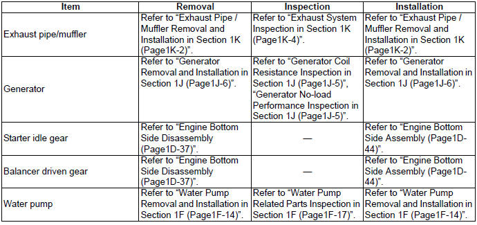
Engine Components Removable with the Engine in Place
Engine components which can be removed while the engine is installed on the frame are as follows. For the installing and removing procedures, refer to respective paragraphs describing each component.
Center of Engine
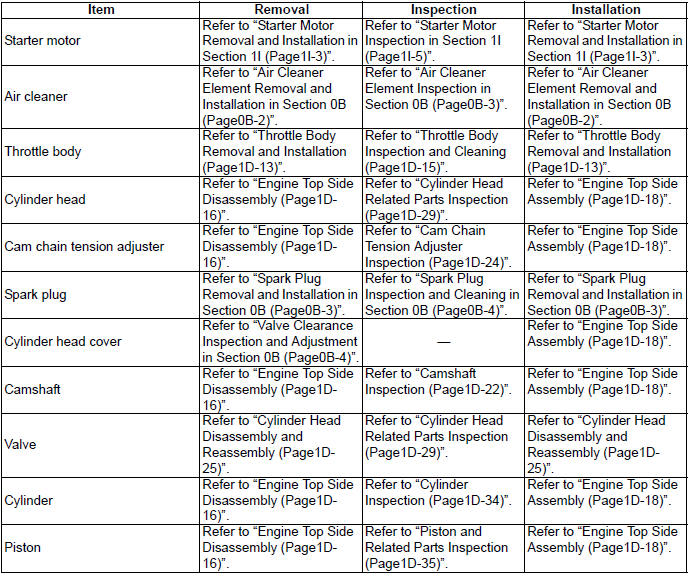
Engine Left Side
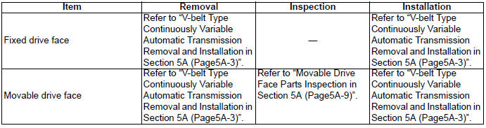
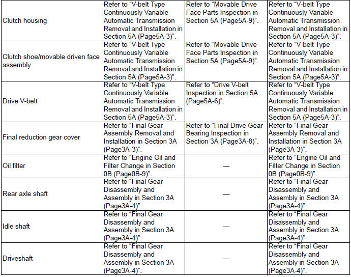
Engine Right Side
Engine Assembly Removal and Installation
Removal
Remove the engine from the frame in the following procedures:
1) Drain engine oil. Refer to "Engine Oil and Filter Change".
2) Drain engine coolant. Refer to "Cooling System Inspection".
3) Drain final reduction gear oil. Refer to "Final Reduction Gear Oil Replacement ".
4) Remove the under cover. Refer to "Under Cover Removal and Installation".
5) Remove the left and right footboards. Refer to "Footboard Removal and Installation".
6) Remove the air cleaner box. Refer to "Air Cleaner Box Removal and Installation".
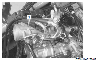
7) Remove the throttle body (1) from the intake pipe.
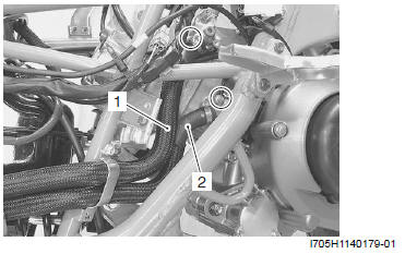
8) Disconnect the radiator hoses (1) and (2).
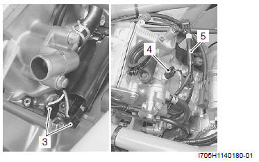
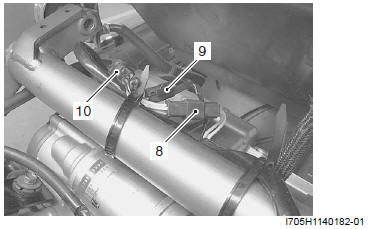
9) Disconnect the ignition coil lead wires (3).
10) Disconnect the ECT sensor coupler (4) and remove the wire harness (5) (for the ignition coil, ECT sensor and IAT sensor).
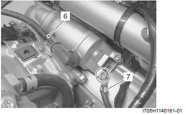
11) Disconnect the starter motor lead wire (6) and engine ground lead wire (7).
12) Disconnect the generator coupler (8), CKP sensor coupler (9) and HO2 sensor coupler (10).
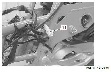
13) Remove the speed sensor coupler (11).
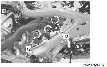
14) Loosen the muffler connecting bolt (12) and remove the exhaust pipe bolts (13).
15) Remove the exhaust pipe/muffler by removing the muffler mounting bolts.
16) Remove the exhaust pipe gasket.
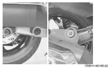
17) Remove the brake hose clamps and rear brake caliper from the swingarm.
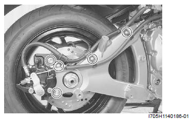
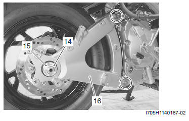
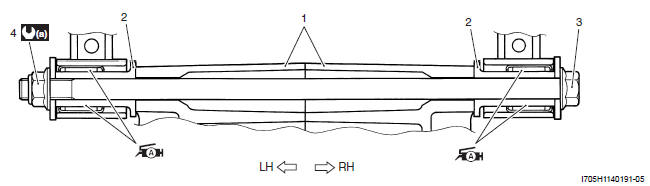
18) Remove the rear axle nut (14) and collar (15).
19) Remove the swingarm (16).
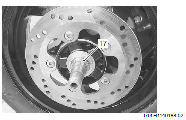
20) Remove the collar (17) and rear wheel.
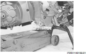
21) Support the engine using an engine jack.
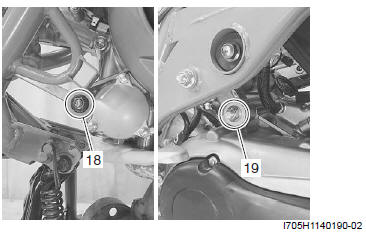
22) Remove the cushion rod bolt/nut (18) and engine mounting bolt/nut (19).
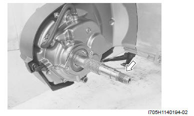
23) Remove the engine from the frame.
Installation
Install the engine in the reverse order of removal. Pay attention to the following points:
- Crankcase
- Collar
- Engine mounting bolt
- Engine mounting nut
 a : 93 N*m (9.3 kgf-m,
67.0 lb-ft)
a : 93 N*m (9.3 kgf-m,
67.0 lb-ft)
 : Apply grease.
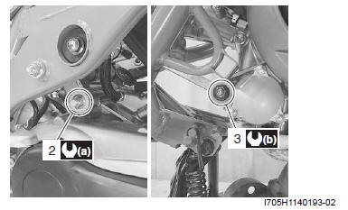
- Tighten the engine mounting nut (2) to the specified torque.
Tightening torque
Engine mounting nut (a): 93 N*m (9.3 kgf-m, 67.0 lb-ft) - Tighten the cushion rod nut (3) to the specified torque.
Tightening torque
Cushion rod nut (b): 85 N*m (8.5 kgf-m, 61.5 lb-ft)
- Make sure that the thread of axle shaft is clean from any greasy matter.
- Install the rear wheel. Refer to "Rear Wheel Assembly Removal and Installation".
- Tighten the rear axle nut to the specified torque.
Tightening torque
Rear axle nut: 120 N*m (12.0 kgf-m, 87.0 lb-ft) - Install the exhaust pipe/muffler. Refer to "Exhaust Pipe / Muffler Removal and Installation".
Crankcase bracket Removal and Installation
Refer to "Crankcase Bracket Removal and Installation".
Crankcase bracket Inspection
Refer to "Crankcase Bracket Related Parts Inspection".
See also:
 Suzuki Burgman 400 - Service manual > Precautions
Precautions for Engine Mechanical Refer to "General Precautions". Schematic and Routing Diagram Camshaft and Sprocket Assembly Diagram 23 N*m (2.3 kgf-m, 16.5 lb-ft) 10 N*m (1.0 kgf-m, 7.0 lb-ft)
Suzuki Burgman 400 - Service manual > Air Cleaner
Air Cleaner Box Removal and Installation Removal 1) Remove the helmet box front cover. Refer to "Helmet Box Front Cover Removal and Installation".


