 Vespa GTS Super 300 ie - Service manual > Rules
This section describes general safety rules for any maintenance operations performed on the vehicle.
Safety rules
- If work can only be done on the vehicle with the engine running, make sure that the premises are well ventilated, using special extractors if necessary; never let the engine run in an enclosed area. Exhaust fumes are toxic.
- The battery electrolyte contains sulphuric acid. Protect your eyes, clothes and skin. Sulphuric acid is highly corrosive; in the event of contact with your eyes or skin, rinse thoroughly with abundant water and seek immediate medical attention.
- The battery produces hydrogen, a gas that can be highly explosive. Do not smoke and avoid sparks or flames near the battery, especially when charging it.
- Fuel is highly flammable and it can be explosive given some conditions. Do not smoke in the working area, and avoid naked flames or sparks.
- Clean the brake pads in a well-ventilated area, directing the jet of compressed air in such a way that you do not breathe in the dust produced by the wear of the friction material. Even though the latter contains no asbestos, inhaling dust is harmful.
Maintenance rules
- Use original PIAGGIO spare parts and lubricants recommended by the Manufacturer. Non-original or non-conforming spares may damage the vehicle.
- Use only the appropriate tools designed for this vehicle.
- Always use new gaskets, sealing rings and split pins upon refitting.
- After removal, clean the components using non-flammable or low flash-point solvents. Lubricate all the work surfaces, except tapered couplings, before refitting these parts.
- After refitting, make sure that all the components have been installed correctly and work properly.
- Use only equipment with metric sizes for removal, service and reassembly operations. Metric bolts, nuts and screws are not interchangeable with coupling members using English measurements. Using unsuitable coupling members and tools may damage the vehicle.
- When carrying out maintenance operations on the vehicle that involve the electrical system, make sure the electrical connections have been made properly, particularly the ground and battery connections.
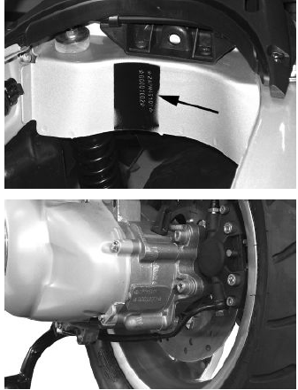
Vehicle identification
Chassis prefix: ZAPM45100000 ÷ 1001
Engine prefix: M451M ÷ 1001
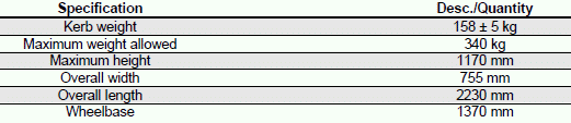
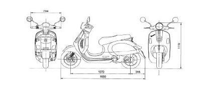
Dimensions and mass
WEIGHTS AND DIMENSIONS
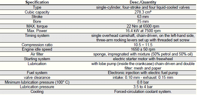
Engine
DATA
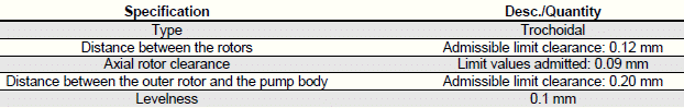
OIL PUMP
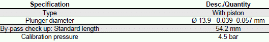
BY-PASS
OIL FILTER

OIL MINIMUM PRESSURE INDICATOR LIGHT SWITCH

HEAD LUBRICATION CONTROL JET

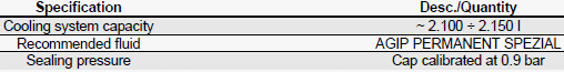
COOLING SYSTEM
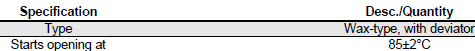
THERMOSTAT
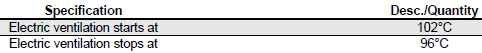
ELECTRIC VENTILATION
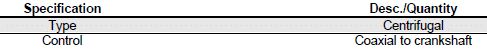
WATER PUMP
RADIATOR

Transmission
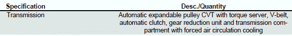
TRANSMISSION
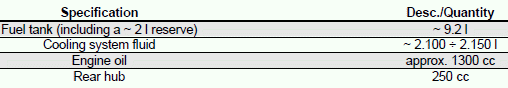
Capacities
CAPACITY
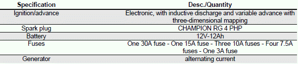
Electrical system
ELECTRICAL COMPONENTS
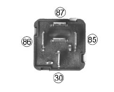
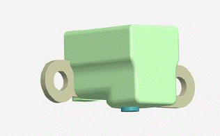
CHECKING REMOTE CONTROLS "A" OPERATING AS CIRCUIT BREAKERS
1) Check that, given regular conditions, there is no continuity between terminals 30 and 87.
2) Apply 12V voltage to power terminals 85 and 86 of the remote control.
3) With the remote control powered, check that there is continuity between terminals 30 and 87.
4) If these conditions are not fulfilled, the remote control is damaged and must be replaced.
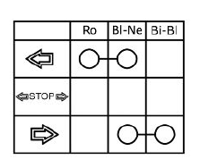
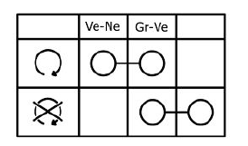
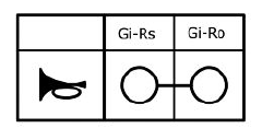
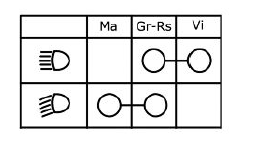
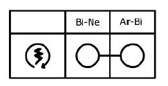
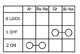
To check buttons and switches, check that, according to their position, the continuity of contacts is correct as indicated in the following charts.
TURN INDICATOR SWITCH
ENGINE STOP SWITCH
HORN BUTTON
LIGHT SWITCH
STARTER BUTTON
IGNITION KEY
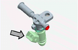
FUEL INJECTOR
Type: 3 holes
Conicity of the nozzle: 20º
Resistance at terminals: 13.7 - 15.2 Ohm
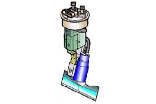
FUEL PUMP UNIT
Mechanical type pressure regulator operating at a pressure of 2.5 BAR
Pump winding resistance: - 1.5 Ohm
Input current during regular functioning: 1.4 - 1.8 A
SPEED/PHASE SENSOR
Resistance between pins 13 and 15: 100 to 150 Ohm at approx. 20º
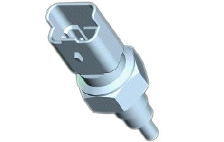
ENGINE TEMPERATURE SENSOR
0º = 5900 Ohm
+10º = 3800 Ohm
+20º = 2500 Ohm
+30º = 1700 Ohm
+80º = 300 Ohm
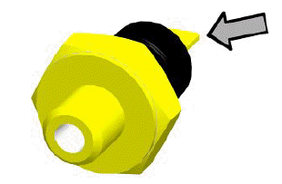
MINIMUM OIL PRESSURE SENSOR
Normally closed switch
Activation threshold: 0.3 - 0.6 BAR
With the engine off: continuity between terminal and ground
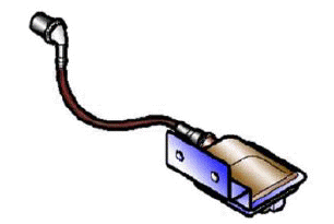
HV COIL
<DIV class=O v:shape="_x0000_s3074">
- Resistance of the primary = 0.5 Ohm +- 8%
- Resistance between primary and ground = infinite
- Resistance between primary and HV output = 3.1 KOhm +- 9%
- Presence of battery voltage between pins 22 and 26 of the interface cable harness upon shifting to ON and for 2 sec.
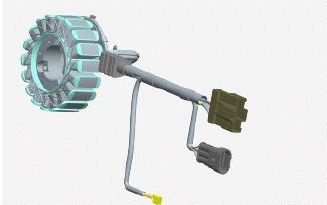
STATOR
Power: 450 W
Resistance between terminals: 0.2 - 1 Ohm terminal insulation from ground
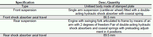
Frame and suspensions
CHASSIS AND SUSPENSIONS
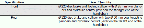
Brakes
BRAKES
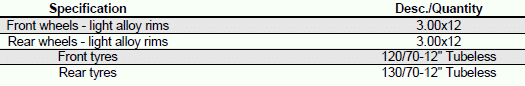
Wheels and tyres
WHEELS AND TYRES
TYRE PRESSURE
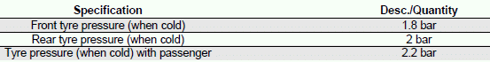
N.B.
CHECK AND ADJUST TYRE PRESSURE WITH TYRES AT AMBIENT TEMPERATURE. REGULATE PRESSURE ACCORDING TO THE WEIGHT OF BOTH RIDER AND ACCESSORIES
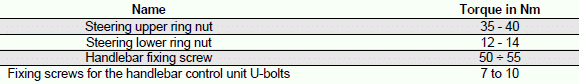
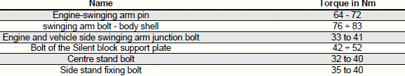
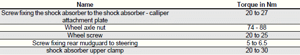
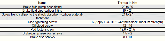
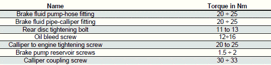
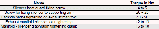
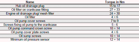
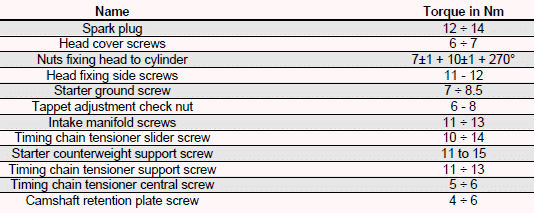
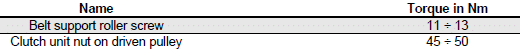
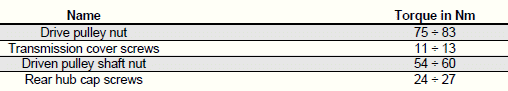
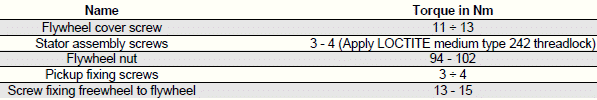
Tightening Torques
STEERING ASSEMBLY
CHASSIS ASSEMBLY
FRONT SUSPENSION
FRONT BRAKE
REAR SUSPENSION
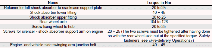
REAR BRAKE
SILENCER
LUBRICATION
CYLINDER HEAD
TRANSMISSION
FLYWHEEL
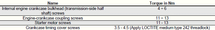
CRANKCASE AND CRANKSHAFT
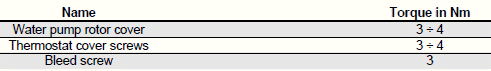
COOLING
See also:
 Vespa GTS Super 300 ie - Service manual > Overhaul data
Assembly clearances Cylinder - piston assy.


