 Vespa GTS Super 300 ie - Service manual > Starter motor
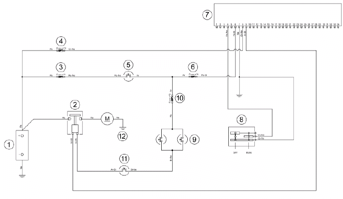
KEY
1. Battery
2. Starter relay
3. Fuse No. 1
4. Fuse No. 2
5. Key switch contacts
6. Fuse No. 5
7. Electronic control unit
8. Engine stop switch
9. Stop buttons
10. Fuse No. 6
11. Starter button
12. Starter motor
WARNING
ALL CONTINUITY TESTS MUST BE CARRIED OUT WITH THE CORRESPONDING CONNECTORS DISCONNECTED.
1) Check fuses No. 1,2,5 and 6.
2) Check key switch contacts.
3) Check the contacts of the stop buttons and the starter button.
4) With the ignition key set to "ON", the brake pulled and the starter button pressed, check if there is voltage between the Orange-White cable of the start-up remote control switch and the ground connection.
If there is not, check the cable harnesses.
5) Check the starter relay.
6) Check that the Red cable between the battery and the starter relay is not interrupted. Also check continuity between the latter and the starter motor.
7) Check the starter motor ground connection.
8) Check that the Orange-Blue cable between the start-up remote control switch and the control unit (pin 9) is not interrupted.
9) Check the contacts of the engine stop switch and that the Green-Black cable connecting this switch to the control unit (pin 4) is not interrupted.
10) Check the engine stop switch ground connection.
Horn control
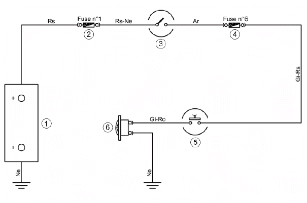
KEY
- Battery
- Fuse No. 1
- Key switch contacts
- Fuse No. 6
- Horn button
- Horn
WARNING
ALL CONTINUITY TESTS MUST BE CARRIED OUT WITH THE CORRESPONDING CONNECTORS DISCONNECTED.
1) Check fuses No. 1 and 6.
2) Check the key switch and horn button contacts.
3) With the key switch set to "ON" and the horn button pressed, check if there is voltage between the Yellow-Pink cable of the horn device and the ground connection. If there is not, check the cable harnesses.
4) Check the horn device ground connection.
Turn signals system check
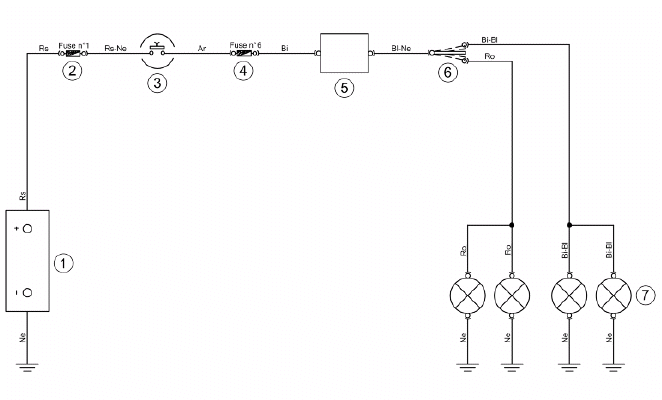
KEY
- Battery
- Fuse No. 1
- Key switch contacts
- Fuse No. 6
- Turn indicator control device
- Turn indicator switch
- Turn indicator bulbs
WARNING
ALL CONTINUITY TESTS MUST BE CARRIED OUT WITH THE CORRESPONDING CONNECTORS DISCONNECTED.
1) Check that bulbs operate properly.
2) Check fuses No. 1 and 6.
3) Check key switch contacts.
4) With the ignition key set to "ON", check if there is voltage between the Blue-Black cable of the turn indicators switch and the ground connection. If there is not, check the cable harnesses and the connections of the turn indicator control device.
5) Check the turn indicator switch contacts.
6) With the turn indicator switch pressed to the right, check if there is voltage between the White-Blue cable of the switch and the ground connection. If there is not, check the cable harnesses.
7) With the turn indicator switch pressed to the left, check if there is voltage between the Pink cable of the switch and the ground connection. If there is not, check the cable harnesses.
8) Check that the cable harnesses of the bulbs and their ground connection are not interrupted.
level indicators
WARNING
ALL CONTINUITY TESTS MUST BE CARRIED OUT WITH THE CORRESPONDING CONNECTORS DISCONNECTED.
If faults are detected:
1) With a multimeter, check resistance values between the White-Green cable and the Black cable of the fuel level transmitter under different conditions.
2) If the transmitter operates correctly but the indication on the instrument panel is not exact, check that the cable harnesses between them are not interrupted.
See also:
 Vespa GTS Super 300 ie - Service manual > Checks and inspections
This section is dedicated to the checks on the electrical system components. Immobiliser The electronic ignition system is controlled by the control unit with the integrated Immobilizer system.
Vespa GTS Super 300 ie - Service manual > Electric characteristic
Resistance value when the tank is full <= 7 Ω Resistance value when the tank is empty 90 +13/-3 Ω Lights list


