 Vespa GTS Super 300 ie - Service manual > Checks and inspections
This section is dedicated to the checks on the electrical system components.
Immobiliser
The electronic ignition system is controlled by the control unit with the integrated Immobilizer system.
The immobiliser is an antitheft system which allows the vehicle to function only if it is activated by means of the coded keys that the control unit recognises. The code is integrated in a transponder in the key block. This allows the driver clear operation without having to do anything other than just turning the key. The Immobilizer system consists of the following components:
- Control unit
- Immobilizer aerial
- master and service keys with built-in transponder
- HV coil.
- diagnosis LED
The diagnosis LED also works as a theft-deterrent blinker. This function is activated every time the ignition switch is turned to the "OFF" position, or the emergency stop switch is turned to the "OFF" position. It remains activated for 48 hours in order not to affect the battery charge.
When the ignition switch is turned to "ON", it interrupts the function of the immobiliser lamp and a start enable lamp comes "ON".
The duration of the flash depends on the programming of the electronic control unit.
If the LED is off regardless of the position of the ignition switch and/or the instrument panel is not initiated, check if:
- there is battery voltage
- that fuse 1 and fuse 5 are in good conditions.
- there is power to the control unit as specified below:
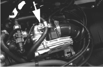
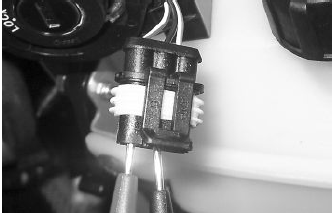
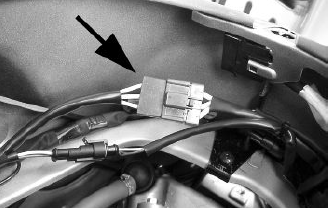
Remove the connector mounting bracket shown in the photograph and disconnect the connector from the control unit. Check the following conditions:
With the key switch set to OFF:
- there is battery voltage between terminals 7-9 and terminal 9-chassis ground (fixed power supply). If there is no voltage check that fuse 2 and its cable are in working order.
With the key switch in the ON position:
- there is battery voltage between terminals 6-7 and terminal 6-chassis ground (fixed power supply). If there is no voltage, check the key switch contacts, that fuse 5 and its cable are in working order.
- There is continuity between terminals 4-19 and 4-33 with the emergency cut-out switch in the RUN position. If there is no continuity, check the contacts of the latter.
If no faults are found, replace the control unit.
After removing the leg shield back plate, remove the electrical connection from the aerial as shown in the picture.
Remove the protective base from the connector.
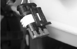
With the ignition switch at ON check there is battery voltage between the Red-White and Black cables
Virgin circuit
When the ignition system is not encrypted, any key will start the engine but limited to 2000 rpm. The keys can only be recognised if the control unit has been programmed properly.
The data storage procedure for a previously unprogrammed control unit provides for the recognition of the red key (master key) as the first key to be stored to memory: this becomes particularly important because it is the only key that enables the control unit to be wiped clean and reprogrammed for the memorisation of the service keys.
The master and service keys must be used to code the system as follows:
- Insert the Master key, turn it to "ON" and keep this position for two seconds (lower and upper limits 1 to 3 seconds).
- Insert the blue key and set to "ON" for 2 seconds.
- If you have copies of the key, repeat the operation with each key.
- Insert the MASTER key again and turn it to "ON" for 2 seconds.
The maximum time to change keys is 10 seconds.
A maximum of 7 service keys (blue) can be programmed at one time.
It is essential to adhere to the times and the procedure.
If you do not, start again from the beginning.
Once the system has been programmed, master key transponder, decoder and control unit are strictly matched.
With this link established, it is now possible to encode new service keys, in the event of losses, replacements, etc.
Each new programming deletes the previous one so, in order to add or eliminate keys, you must repeat the procedure using all the keys you intend to keep using.
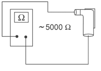
If a service key becomes uncoded, the efficiency of the high voltage circuit shielding must be thoroughly inspected. In any case it is advisable to use resistive spark plugs.
Characteristic
Shielded cap resistance
- 5000 Ω.
Diagnostic codes
The Immobilizer system is tested each time the ignition key is turned from "OFF" to "ON". During this diagnosis phase a number of control unit statuses can be identified and various light codes displayed. Regardless of the code transmitted, if at the end of the diagnosis the LED remains off permanently, the ignition is enabled. If, however, the LED remains on permanently, it means the ignition is inhibited:
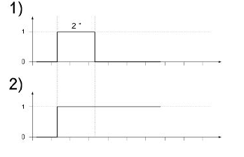
1. Previously unused control unit - key inserted: a single 2 second flash is displayed, after which the LED remains off permanently. The keys can be stored to memory, the vehicle can be started but with a limitation imposed on the number of revs.
2. Previously unused control unit - transponder absent or cannot be used: the LED is on permanently. In this condition no operations are possible including the start up of the vehicle.
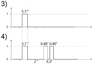
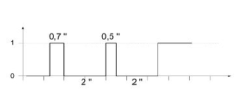
3. Programmed control unit - the service key in (normal condition of use): a single 0.7-second flash is displayed, after which the LED remains off steadily. The engine can be started.
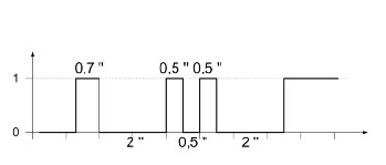
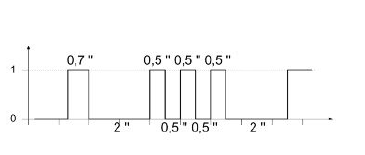
4. Programmed control unit - Master key in: a 0.7-sec flash is displayed followed by the LED remaining off for 2 sec and then by short 0.46-sec flashes, the same number of times as there are keys stored in the memory including the Master key. When the diagnosis has been completed, the LED remains permanently OFF. The engine can be started.
5. Programmed control unit - fault detected: a light code is displayed according to the fault detected, after which the LED remains on steadily. The engine cannot be started. The codes that can be transmitted are:
- 1-flash code
- 2-flash code
- 3-flash code
Diagnostic code - 1 flash
A one-flash code indicates a system where the serial line is not present or is not detected. Check the Immobilizer antenna wiring and change it if necessary.
Diagnostic code - 2 flashes
A two-flash code shows a system where the control unit does not show the transponder signal. This might depend on the inefficiency of the immobilizer antenna or the transponder.
Turn the switch to ON using several keys: if the code is repeated even with the Master key, check the aerial wiring and change it if necessary. If this is not the case, replace the defective key and/or reprogram the control unit. Replace the control unit if the problem continues.
Diagnostic code - 3 flashes
A three-flash code indicates a system where the control unit does not recognise the key. Turn the switch to ON using several keys: if the error code is repeated even with the Master key, replace the control unit. If this is not the case, reprogram the decoder.
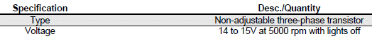
Battery recharge circuit
The charging circuit consists of three-phase alternator and a permanent magneto flywheel.
The generator is directly connected to the voltage regulator.
This, in its turn, is connected directly to the ground and the battery positive terminal passing through the 30A protective fuse.
The three-phase alternator provides good recharge power and at low revs a good compromise is achieved between generated power and idle stability.
Stator check
Checking the stator windings
WARNING
THIS CHECK-UP CAN BE MADE WITH THE STATOR PROPERLY INSTALLED.
1) Lift the saddle and remove the helmet compartment.
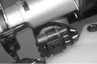
2) Disconnect the connector between stator and regulator with the three yellow cables as shown in the picture.
3) Measure the resistance between each of the yellow terminals and the other two.
Electric characteristic
Resistance:
0.2 - 1 Ω
4) Check that there is insulation between the each yellow cable and the ground.
5) If values are incorrect, replace the stator.
Recharge system voltage check
Look for any leakage
1) Access the battery by removing the cover in the footrest.
2) Check that the battery does not show signs of losing fluid before checking the output voltage.
3) Turn the ignition key to position OFF, connect the terminals of the tester between the negative pole (-) of the battery and the black cable and only then disconnect the black cable from the negative pole (-) of the battery.
4) With the ignition key always at OFF, the reading indicated by the ammeter must be ≤ 0.5 mA.
Charging current check
WARNING
BEFORE CARRYING OUT THE CHECK, MAKE SURE THAT THE BATTERY IS IN GOOD WORKING ORDER.
1) Place the vehicle on its centre stand
2) With the battery correctly connected to the circuit, place the multimeter leads between the battery terminals.
3) Start the engine, ensure that the lights are all out, increase the engine speed and at the same time measure the voltage.
Electric characteristic
Voltage ranging between 14.0 and 15.0V at 5000 rpm.
Maximum current output check.
- With engine off and panel set to "ON" turn on the lights and let the battery voltage set to 12V.
- Connect ammeter pliers to the 2 recharge positive poles in output from the regulator.
- Keep the lights on and start the engine, bring it to normal speed and read the values on the ammeter.
With an efficient battery a value must be detected: > 20A
VOLTAGE REGULATOR/RECTIFIER
See also:
 Vespa GTS Super 300 ie - Service manual > Conceptual diagrams
Ignition KEY 1. 12v-10Ah battery 7. Fuse No. 1 - 30A 8. Fuse No. 5 - 7.5A 9. Fuse No. 2 - 15A 10. Fuses No. 6 - 7.5A 11. Fuse No. 3 - 15A 12. Fuse No. 4 - 7.5A 14. Key switch contacts 15. Engine stop switch 18. Injection load relay 25. H.V. coil. 29. Diagnosis socket 30. Injection electronic control unit 31. Immobilizer antenna 34. Instrument panel
Vespa GTS Super 300 ie - Service manual > Starter motor
KEY 1. Battery 2. Starter relay 3. Fuse No. 1 4. Fuse No. 2 5. Key switch contacts 6. Fuse No. 5 7. Electronic control unit 8. Engine stop switch 9. Stop buttons 10. Fuse No. 6 11. Starter button 12. Starter motor


