 Vespa GTS Super 300 ie - Service manual > Conceptual diagrams
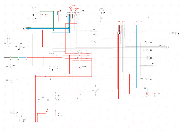
Ignition
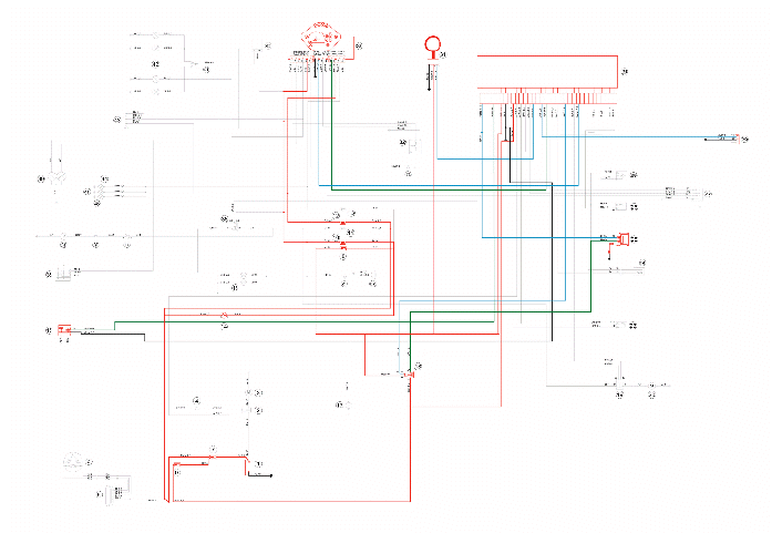
KEY
1. 12v-10Ah battery
7. Fuse No. 1 - 30A
8. Fuse No. 5 - 7.5A
9. Fuse No. 2 - 15A
10. Fuses No. 6 - 7.5A
11. Fuse No. 3 - 15A
12. Fuse No. 4 - 7.5A
14. Key switch contacts
15. Engine stop switch
18. Injection load relay
25. H.V. coil.
29. Diagnosis socket
30. Injection electronic control unit
31. Immobilizer antenna
34. Instrument panel
Battery recharge and starting
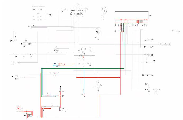
KEY
1. 12v-10Ah battery
2. Starter relay
3. Starter motor
4. Starter button
5. Voltage regulator
6. Magneto flywheel
7. Fuse No. 1 - 30A
8. Fuse No. 5 - 7.5A
9. Fuse No. 2 - 15A
10. Fuses No. 6 - 7.5A
14. Key switch contacts
16. N.2 stop buttons
17. Brake lamp 12v-16w
30. Injection electronic control unit
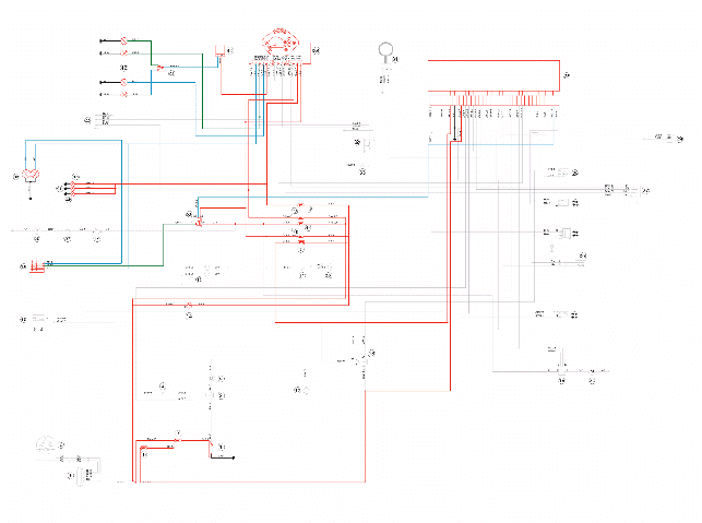
Level indicators and enable signals section
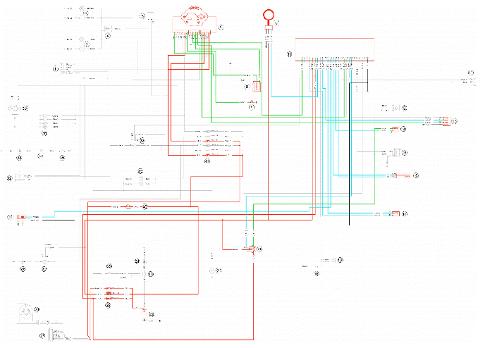
KEY
1. 12v-10Ah battery
7. Fuse No. 1 - 30A
8. Fuse No. 5 - 7.5A
9. Fuse No. 2 - 15A
10. Fuses No. 6 - 7.5A
14. Key switch contacts
15. Engine stop switch
23. Lambda probe
24. Engine speed sensor
27. Engine temperature sensor
30. Injection electronic control unit
31. Immobilizer antenna
32. Fuel level transmitter
33. Oil pressure sensor
34. Instrument panel
Devices and accessories
KEY
1. 12v-10Ah battery
7. Fuse No. 1 - 30A
8. Fuse No. 5 - 7.5A
9. Fuse No. 2 - 15A
10. Fuses No. 6 - 7.5A
11. Fuse No. 3 - 15A
12. Fuse No. 4 - 7.5A
14. Key switch contacts
19. Electric fan remote control
20. Radiator electric fan
21. Horn button
22. Horn
30. Injection electronic control unit
34. Instrument panel
37. Saddle opening switch
38. Saddle opening actuator
40. Turn indicator control device
41. Turn indicator switch
43. Pre-installation for anti-theft device
Lights and turn indicators
Key:
1. 12v-10Ah battery
7. Fuse No. 1 - 30A
8. Fuse No. 5 - 7.5A
9. Fuse No. 2 - 15A
10. Fuses No. 6 - 7.5A
11. Fuse No. 3 - 15A
12. Fuse No. 4 - 7.5A
13. Fuse No. 7 - 7.5A
14. Key switch contacts
30. Injection electronic control unit
34. Instrument panel
35. Light switch
36. Headlight relay
39. Headlight with dual light bulb 12v-55w/60w
40. Turn indicator control device
41. Turn indicator switch
42. 4 bulbs for turn indicators 12v-10w
44. 1 front daylight running light bulb 12v-5w
45. 1 rear daylight running light bulb 12v-5w
46. 1 license plate bulb 12v-5w
Injection
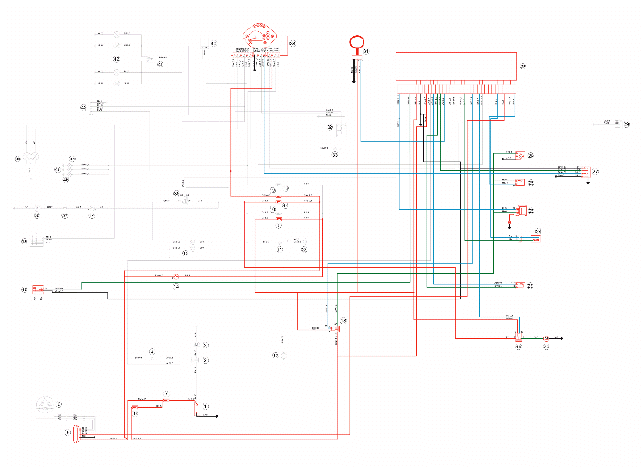
Key:
1. 12v-10Ah battery
7. Fuse No. 1 - 30A
8. Fuse No. 5 - 7.5A
9. Fuse No. 2 - 15A
11. Fuse No. 3 - 15A
12. Fuse No. 4 - 7.5A
14. Key switch contacts
15. Engine stop switch
18. Injection load relay
19. Electric fan remote control
20. Radiator electric fan
23. Lambda probe
24. Engine speed sensor
25. H.V. coil.
26. Fuel injector
27. Engine temperature sensor
28. Fuel pump
30. Injection electronic control unit
31. Immobilizer antenna
34. Instrument panel
See also:
 Vespa GTS Super 300 ie - Service manual > Electrical system installation
Front side Saddle opening switch Pre-installations Insert in clamp Fuse box From the wire unit Front left turn indicator connector Front right turn indicator connector Electric fan connector Turn indicator control device Right turn indicator connector From regulator Wire unit - regulator connection To the immobilizer aerial Light remote control Electric fan remote control To key switch Left turn indicator connector Voltage regulator Immobilizer aerial Foldable clamp to hold cables Battery negative terminal Battery positive terminal Flywheel - regulator connection To stop switch To turn indicator switch To light switch To horn button To instrument panel To headlight To the position light To starter button To the engine stop switch
Vespa GTS Super 300 ie - Service manual > Checks and inspections
This section is dedicated to the checks on the electrical system components. Immobiliser The electronic ignition system is controlled by the control unit with the integrated Immobilizer system.


