 Vespa GTS Super 300 ie - Service manual > Electrical system installation
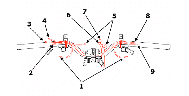
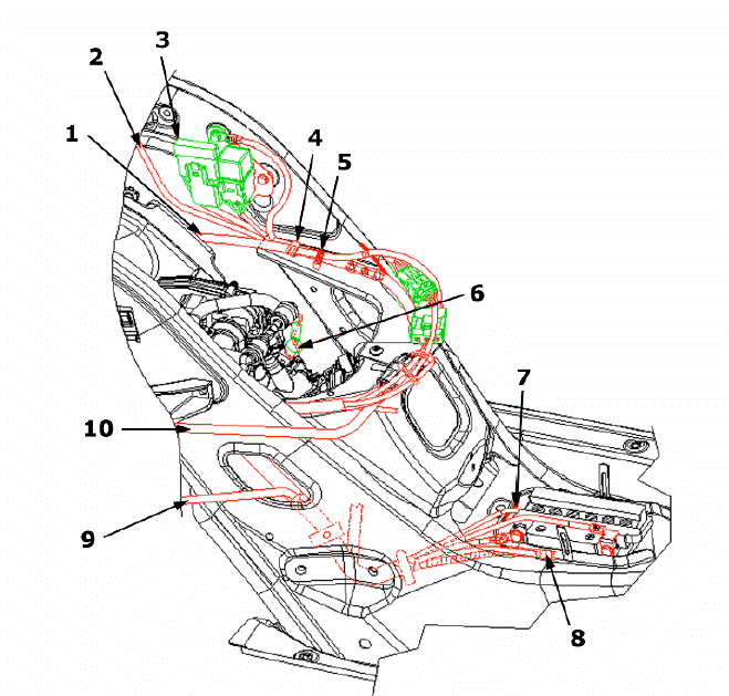
Front side
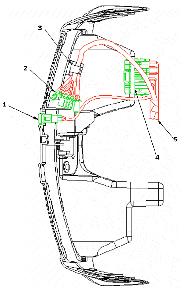
- Saddle opening switch
- Pre-installations
- Insert in clamp
- Fuse box
- From the wire unit
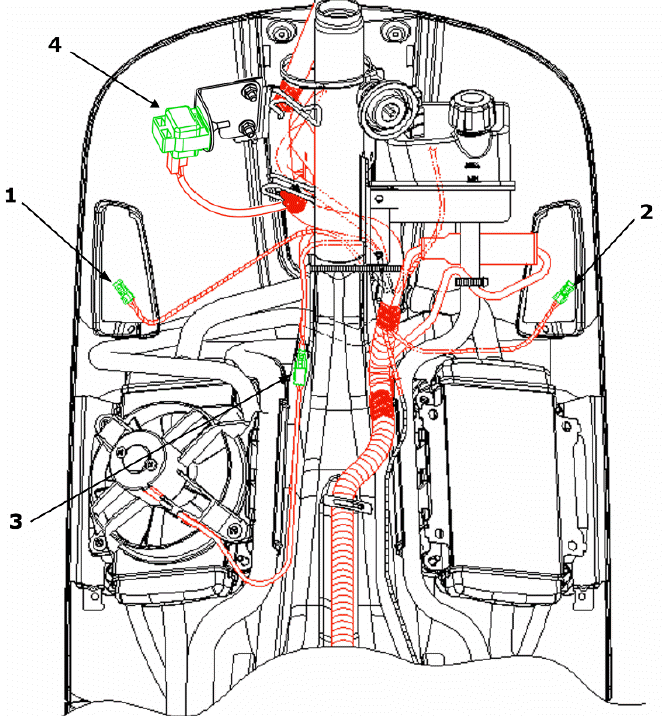
- Front left turn indicator connector
- Front right turn indicator connector
- Electric fan connector
- Turn indicator control device
- Right turn indicator connector
- From regulator
- Wire unit - regulator connection
- To the immobilizer aerial
- Light remote control
- Electric fan remote control
- To key switch
- Left turn indicator connector
- Voltage regulator
- Immobilizer aerial
- Foldable clamp to hold cables
- Battery negative terminal
- Battery positive terminal
- Flywheel - regulator connection
- To stop switch
- To turn indicator switch
- To light switch
- To horn button
- To instrument panel
- To headlight
- To the position light
- To starter button
- To the engine stop switch
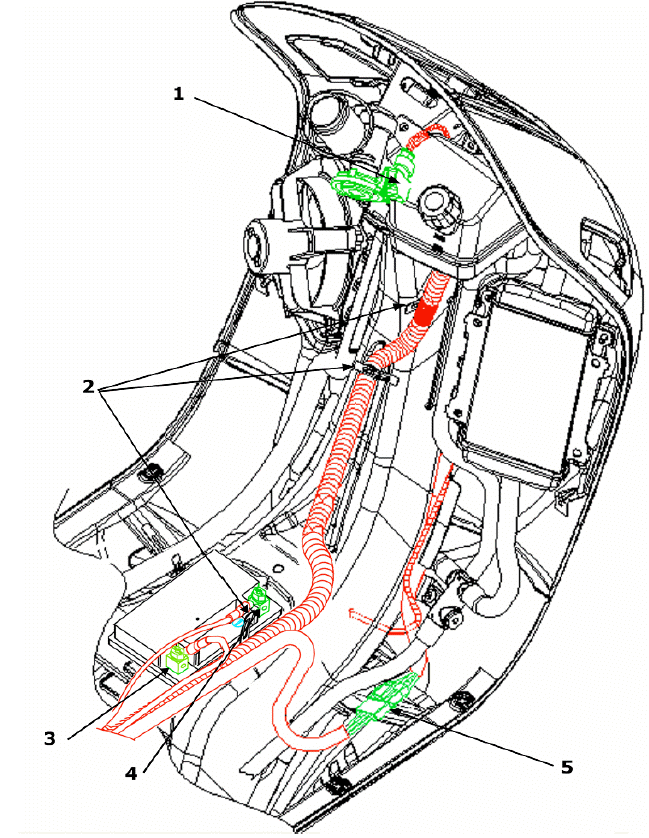
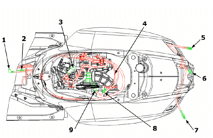
Back side
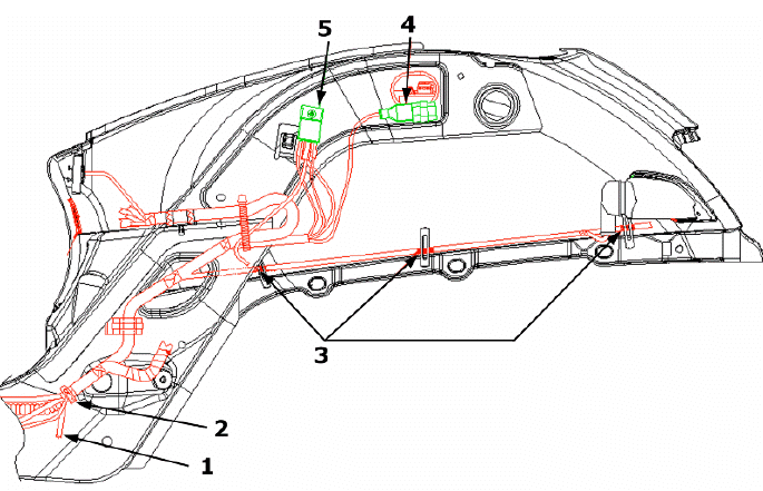
- To HV coil
- Foldable clamp
- Foldable clamps to hold the red sheathing
- Diagnostic socket
- Starter remote control
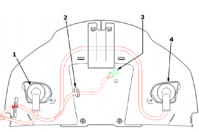
- Rear right turn indicator
- Cable guide
- To rear light
- Rear left turn indicator
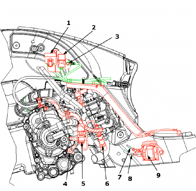
- Fuse box
- Remote control switch
- Ground lead clamping to chassis
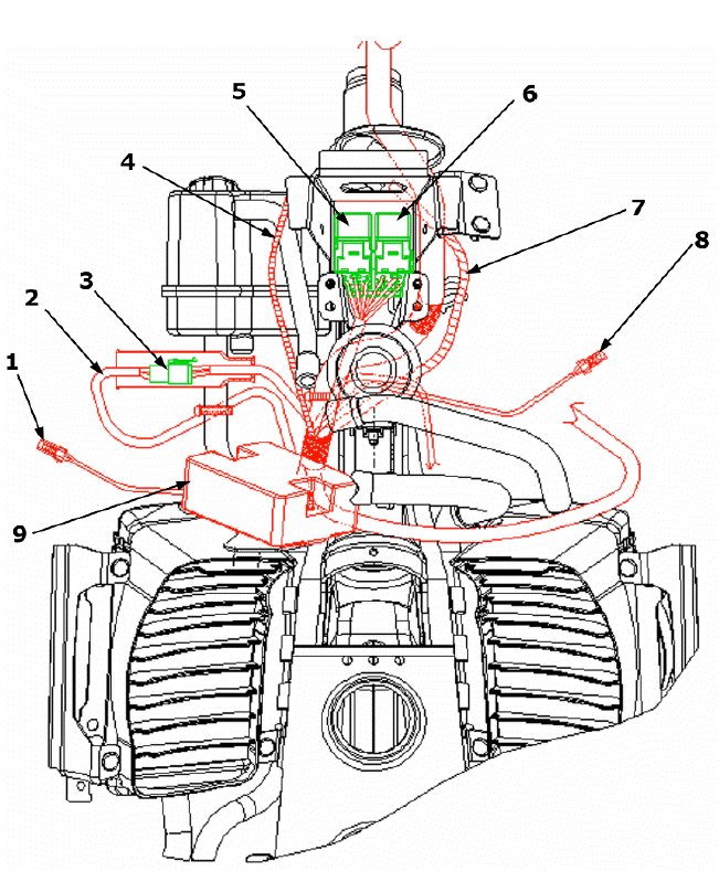
- Oil pressure sensor
- Lambda probe connector
- Lambda sensor
- To wire unit
- To the spark plug
- HV coil
- To flywheel
- To saddle opening actuator
- Fuse box
- Foldable clamp to hold cables
- Clamp
- Injector connector
- To HV coil
- To front wire unit
- To rear turn indicators
- To fuel gauge and fuel tank
- Battery positive terminal
- Battery negative terminal
- Thermistor
- Starter motor ground lead
- Right turn indicator connector
- Rear headlight assembly connector
- Left turn indicator connector
- Starter motor ground lead clamping
- Starter motor positive terminal
See also:
 Vespa GTS Super 300 ie - Service manual > Components arrangement
9. Immobilizer aerial Remove the shield back plate to reach it.
Vespa GTS Super 300 ie - Service manual > Conceptual diagrams
Ignition KEY 1. 12v-10Ah battery 7. Fuse No. 1 - 30A 8. Fuse No. 5 - 7.5A 9. Fuse No. 2 - 15A 10. Fuses No. 6 - 7.5A 11. Fuse No. 3 - 15A 12. Fuse No. 4 - 7.5A 14. Key switch contacts 15. Engine stop switch 18. Injection load relay 25. H.V. coil. 29. Diagnosis socket 30. Injection electronic control unit 31. Immobilizer antenna 34. Instrument panel


