 Vespa GTS Super 300 ie - Service manual > Components arrangement
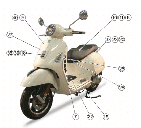
9. Immobilizer aerial
- Remove the shield back plate to reach it.
10. Injection ECU
- Remove the helmet compartment to reach it.
11. Diagnosis connector
- Remove the helmet compartment to reach it.
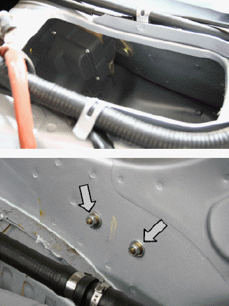
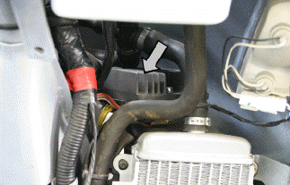
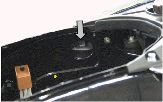
15. H.V. coil
- Remove the battery to reach it; to remove the coil, first remove the footrest and undo the two screws indicated.
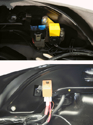
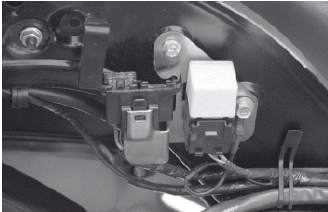
18-30-38 Horn - Remote control switches
- Remove front central cover to reach it.
20-23. Remote control switches
- Remove the front central cover and the helmet compartment to reach them.
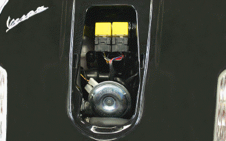
26. Main fuses
- Open the front top box to reach them.
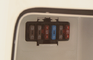
41. Secondary fuse
- Remove the helmet compartment to reach it.
27. Voltage regulator
- Remove the shield back plate to reach it.
28. Magneto flywheel
- Remove the flywheel cover, as described in the "Engine" chapter, to reach it. To get access to the connectors, remove the helmet compartment.
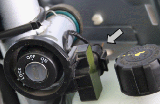
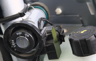
40. Key switch contacts
- Remove the shield back plate to reach them.
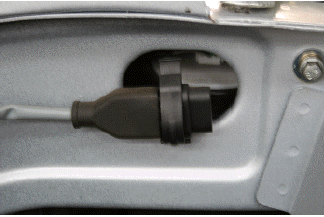
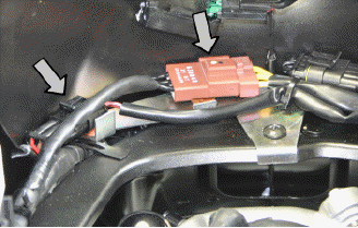
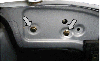
33. Saddle-opening actuator
- Remove the helmet compartment to reach it, undo the two screws indicated and remove the fixing bracket together with the actuator.
8. Fuel level transmitter
- Remove the fuel tank to reach it.
7. Oil pressure sensor
- Remove the right side fairing to reach it.
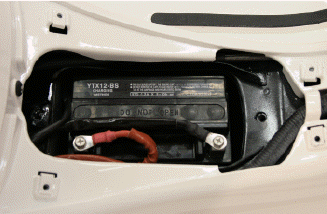
22. Battery
- Remove the rear central cover to reach it.
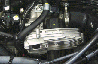
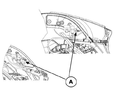
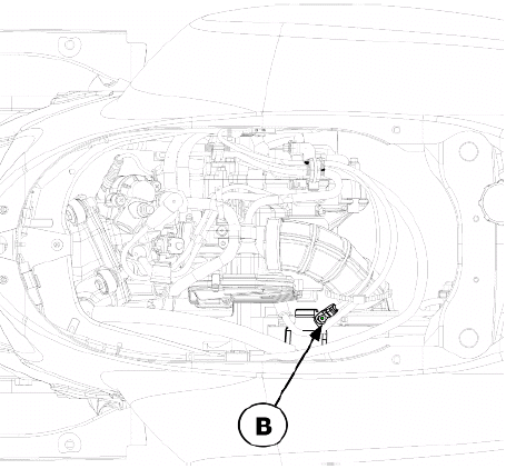
Ground points
On the vehicle there is a ground point on the chassis marked with the letter "A"
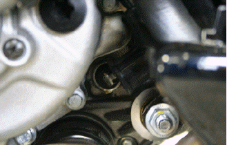
There is another ground point "B" on the starter motor.
See also:
 Vespa GTS Super 300 ie - Service manual > Electrical system installation
Front side Saddle opening switch Pre-installations Insert in clamp Fuse box From the wire unit Front left turn indicator connector Front right turn indicator connector Electric fan connector Turn indicator control device Right turn indicator connector From regulator Wire unit - regulator connection To the immobilizer aerial Light remote control Electric fan remote control To key switch Left turn indicator connector Voltage regulator Immobilizer aerial Foldable clamp to hold cables Battery negative terminal Battery positive terminal Flywheel - regulator connection To stop switch To turn indicator switch To light switch To horn button To instrument panel To headlight To the position light To starter button To the engine stop switch


