 Suzuki Burgman 400 - Service manual > Throttle Cable/Body
Throttle Cable Removal and Installation
Removal
1) Remove the handlebar covers. Refer to "Handlebar Cover Removal and Installation".
2) Remove the front box. Refer to "Front Box Removal and Installation".
3) Remove the front frame cover. Refer to "Front Frame Cover Removal and Installation".
4) Disengage the throttle cable ends from the throttle case on handlebars. Refer to "Handlebars Removal and Installation ".
5) Remove the throttle cables by disengaging the other ends from the throttle body.
Installation
Install the throttle cables in the reverse order of removal.
Pay attention to the following point.
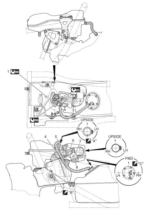
- Rout the throttle cables properly. Refer to "Throttle Cable Routing Diagram".
Throttle Cable Adjustment
Adjust the throttle cable play. Refer to "Throttle Cable Play Inspection and Adjustment ".
Throttle Body Components
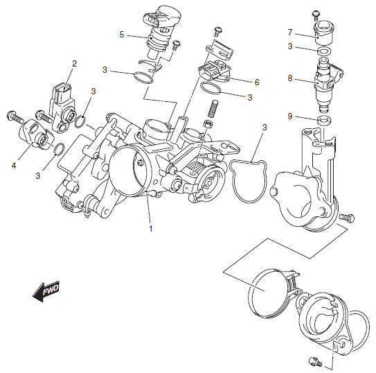
- Throttle body
- TP sensor
- O-ring
- STP sensor
- ISC valve
- IAP sensor
- Insulator
- Fuel injector
- Cushion seal
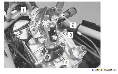
Throttle Body Construction
- ECT sensor
- IAP sensor
- ISC valve
- Fuel injector
- TP sensor
- STP sensor
- STVA
- IAT sensor
- Triangle mark must point downward.
- Tighten the bracket with the cylinder head bolt (L130).
- Tighten each bolt in temporary and final stages in numerical order on bolt.
- 12 N*m (1.2 kgf-m, 8.5 lb-ft)
- 10 N*m (1.0 kgf-m, 7.0 lb-ft)
- 10 N*m (1.0 kgf-m, 7.0 lb-ft)
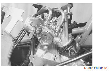
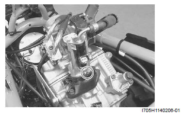
Throttle Body Removal and Installation
Removal
1) Remove the air cleaner box. Refer to "Air Cleaner Box Removal and Installation ".
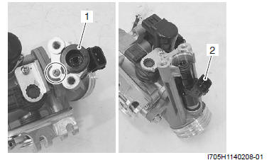
2) Remove the throttle cables (1).
3) Remove the fuel hose (2).
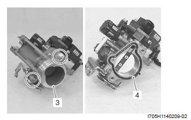
4) Remove the throttle body assembly (3).
5) Remove the intake pipe (4).
Installation
Install the throttle body assembly is in the reverse order of removal. Pay attention to the following points:
- Install the intake pipe. Refer to "Cylinder Disassembly and Assembly ".
- When installing the throttle body to the intake pipe, fit the projection on the throttle body to the depression of the intake pipe.
- Connect the throttle cables properly. Refer to "Throttle Cable Removal and Installation".
- Adjust the throttle cable play. Refer to "Throttle Cable Play Inspection and Adjustment".
Throttle Body Disassembly and Assembly
Disassembly
1) Remove the throttle body. Refer to "Throttle Body Removal and Installation ".
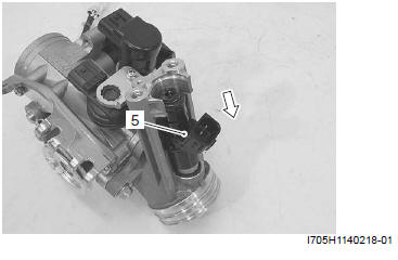
2) Remove the insulator (1) and fuel injector (2).
3) Remove the intake pipe (3) and O-ring (4).
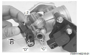
4) Remove the IAP sensor (5) and O-ring (6).
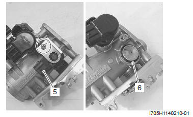
5) Remove the ISC valve (7).
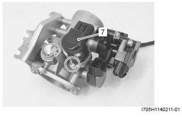
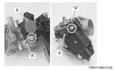
6) Remove the TP sensor (8) and STV sensor (9).
NOTE Prior to disassembly, mark each sensors original position with a paint or scribe "A" for accurate reinstallation.
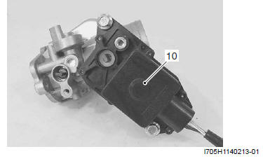
! CAUTION Never remove the STVA (10) from the throttle body.
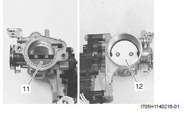
! CAUTION Never remove the throttle valve (11) and secondary throttle valve (12).
Assembly
Assembly is the throttle body in the reverse order of removal. Pay attention to the following points:
- With the STV fully opened, install the STP sensor (1).
! CAUTION Apply thin coat of the engine oil to the O-ring.
NOTE
- Align the secondary throttle shaft end "A" with the groove "B" of STP sensor.
- Apply grease to the secondary throttle shaft end "A".
 : Grease
99000-25010 (SUZUKI SUPER GREASE A or equivalent)
: Grease
99000-25010 (SUZUKI SUPER GREASE A or equivalent)
NOTE Make sure the STP valve open or close smoothly. If the STP sensor adjustment is necessary, refer to "STP Sensor Adjustment".
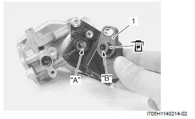
- With the throttle valve fully closed, install the TP sensor (2).
CAUTION Apply thin coat of the engine oil to the O-ring.
NOTE
- Align the throttle shaft end "C" with the groove "D" of TP sensor.
- Apply grease to the secondary throttle shaft end "C".
: Grease
99000-25010 (SUZUKI SUPER GREASE A or equivalent)
NOTE Make sure the TP valve open or close smoothly. If the TP sensor adjustment is necessary, refer to "TP Sensor Adjustment".
- Install the ISC valve. Refer to "ISC Valve Removal and Installation".
- Apply thin coat of the engine oil to the new O-ring (3) and cushion seal (4).
! CAUTION Replace the O-ring and cushion seal with the new ones.

- Install the fuel injector (5) by pushing it straight to the throttle body.
! CAUTION Never turn the fuel injector while pushing it.
Throttle Body Inspection and Cleaning
Refer to "Throttle Body Disassembly and Assembly".
Cleaning
! WARNING Some carburetor cleaning chemicals, especially dip-type soaking solutions, are very corrosive and must be handled carefully.
Always follow the chemical manufacturer's instructions on proper use, handling and storage.
- Clean passageways with a spray-type carburetor cleaner and blow dry with compressed air.
! CAUTION Do not use wire to clean passageways. Wire can damage passageways. If the components cannot be cleaned with a spray cleaner it may be necessary to use a dip-type cleaning solution and allow them to soak. Always follow the chemical manufacturer's instructions for proper use and cleaning of the throttle body components. Do not apply carburetor cleaning chemicals to the rubber and plastic materials.
Inspection
Check following items for any defects or clogging.
- Throttle shafts
- Throttle valve
- Secondary throttle valve
Replace the throttle body if necessary.
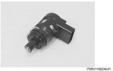
ISC Valve Inspection
Inspect the ISC valve for any carbon deposition defects.
Clean or replace the ISC valve if necessary.
See also:
 Suzuki Burgman 400 - Service manual > Air Cleaner
Air Cleaner Box Removal and Installation Removal 1) Remove the helmet box front cover. Refer to "Helmet Box Front Cover Removal and Installation".
Suzuki Burgman 400 - Service manual > Engine Top
Engine Top Side Disassembly It is unnecessary to remove the engine assembly from the frame when servicing the engine top side. NOTE Before servicing the engine top side with engine inplace, remove the air cleaner box, throttle body, fuel tank, exhaust pipe, muffler and etc. Refer to "Engine Assembly Removal and Installation".


