 Suzuki Burgman 400 - Service manual > Turn Signal / Side-stand Relay Removal and Installation
Refer to "Electrical Components Location".
Removal
1) Remove the meter panel. Refer to "Meter Panel Removal and Installation".
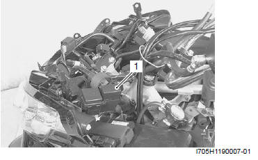
2) Remove the turn signal/side-stand relay (1).
Installation
Install the turn signal/side-stand relay in the reverse order of removal.
Side-stand / Ignition Interlock System Parts Inspection
Refer to "Electrical Components Location".
Check the interlock system for proper operation. If the interlock system does not operate properly, check each component for damage or abnormalities. If any abnormality is found, replace the component with a new one.
Side-stand Switch
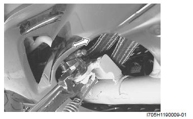
1) Remove the left footboard. Refer to "Footboard Removal and Installation".
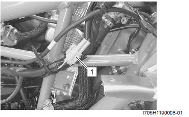
2) Disconnect the side-stand switch coupler (1).
3) Measure the voltage between G and B/W lead wires.
Special tool : 09900-25008 (Multi-circuit tester set)
Tester knob indication
Diode test ( )
)
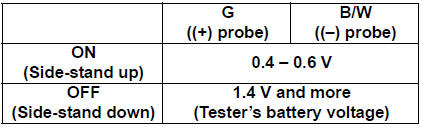
NOTE If the tester reads 1.4 V and below when the tester probes are not connected, replace its battery.
4) Connect the side-stand switch coupler.
5) Install the left footboard. Refer to "Footboard Removal and Installation".
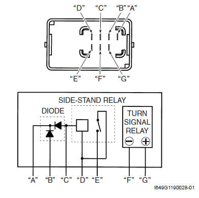
Turn Signal / Side-stand Relay
The turn signal/side-stand relay is composed of the turn signal relay, side-stand relay and diode.
Side-stand relay
1) Remove the turn signal/side-stand relay. Refer to "Turn Signal / Side-stand Relay Removal and Installation".
2) Check the insulation between "D" and "E" terminals using the multi-circuit tester.
3) Apply 12 V to terminals "D" and "C" ( (+) to "D" and (- ) to "C") and check the continuity between "D" and "E". If there is no continuity, replace the turn signal/ side-stand relay with a new one. Refer to "Turn Signal / Side-stand Relay Removal and Installation".
Special tool : 09900-25008 (Multi-circuit tester set)
Tester knob indication
Continuity test ( )
)
4) Install the turn signal/side-stand relay. Refer to "Turn Signal / Side-stand Relay Removal and Installation".
Diode inspection
1) Remove the turn signal/side-stand relay. Refer to "Turn Signal / Side-stand Relay Removal and Installation ".
2) Measure the voltage between the terminals using the multi-circuit tester.
Special tool : 09900-25008 (Multi-circuit tester set)
Tester knob indication
Diode test ( )
)
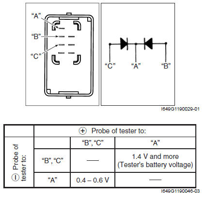
NOTE If the multi circuit tester reads 1.4 V and below when the tester probes are not connected, replace its battery.
3) Install the turn signal/side-stand relay. Refer to "Turn Signal / Side-stand Relay Removal and Installation".
Starter Clutch Component
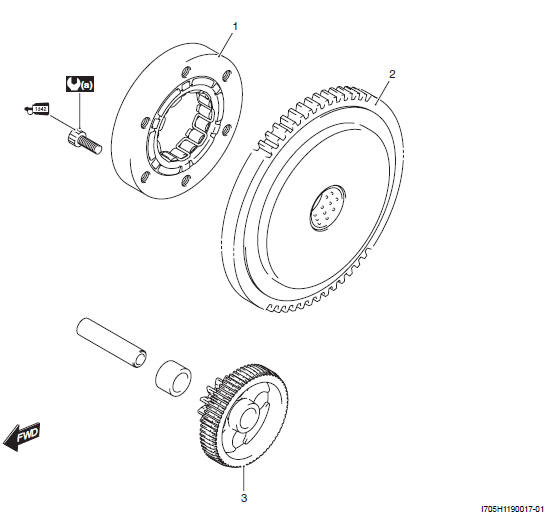
- One-way clutch
- Starter driven gear
- Starter idle gear
 : Apply thread lock
to thread part.
: Apply thread lock
to thread part.
 a : 26 N*m (2.6
kgf-m, 19.0 lb-ft)
a : 26 N*m (2.6
kgf-m, 19.0 lb-ft)
Starter Clutch Removal and Installation
Removal
1) Drain engine oil. Refer to "Engine Oil and Filter Change ".
2) Remove the muffler. Refer to "Exhaust Pipe / Muffler Removal and Installation".
3) Remove the generator cover (1).
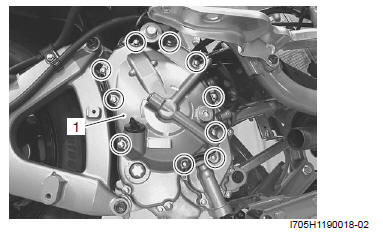
4) Remove the generator rotor and starter driven gear.
Refer to "Engine Bottom Side Disassembly".
Installation
Install the starter clutch in the reverse order of removal.
Pay attention to the following points:
- Install the generator rotor. Refer to "Engine Bottom Side Assembly".
- Replace the generator cover gasket with a new one.
- Install the muffler. Refer to "Exhaust Pipe / Muffler Removal and Installation".
- Pour engine oil. Refer to "Engine Oil and Filter Change".
Starter Clutch Inspection
Inspect the starter clutch in the following procedures.
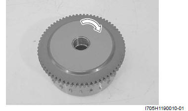
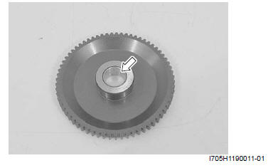
1) Install the starter driven gear onto the starter clutch and turn the starter driven gear by hand to inspect the starter clutch for a smooth movement. The gear turns one direction only. If a large resistance is felt to rotation, inspect the starter clutch for damage or inspect the starter clutch contacting surface of the starter driven gear for wear or damage.
If they are found to be damaged, replace them with the new ones.
2) Inspect the starter driven gear bearing for any damages.
Starter Clutch Disassembly and Assembly
Disassembly
1) With the rotor held with a wrench, loosen the starter clutch bolts.
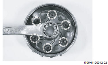
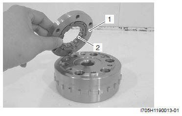
2) Remove the one-way clutch guide (1) and one-way clutch (2) from the rotor.
Reassembly
Reassemble the starter clutch in the reverse order of disassembly. Pay attention to the following points:
- When inserting the one-way clutch (1) into the one-way clutch guide (2), the flange side "A" must be positioned on the rotor side "B".
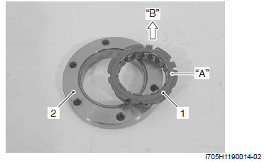
- One-way clutch
- One-way guide
- Flange
- Rotor side
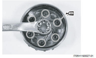
- Apply thread lock on the starter clutch bolts and tighten them to the specified torque.
Tightening torque
Starter clutch bolt: 26 N*m (2.6 kgf-m, 19.0 lb-ft)
: Thread lock
cement 99000-32050 (THREAD LOCK CEMENT 1342 or equivalent)
! CAUTION After installing the starter driven gear, check that the clutch functions properly.
Starter Button Inspection
Refer to "Starter Button Inspection".
Specifications
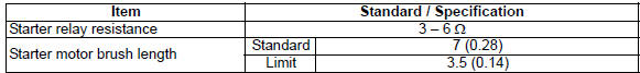
Service Data
Electrical
Unit: mm (in)
Tightening Torque Specifications
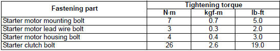
NOTE The specified tightening torque is also described in the following.
Reference: For the tightening torque of fastener not specified in this section, refer to "Tightening Torque Specifications".
Special Tools and Equipment
Recommended Service Material
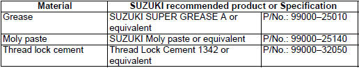
NOTE Required service material is also described in the following.
Special Tool
 09900-20102
Vernier calipers (1/20 mm, 200 mm)
09900-20102
Vernier calipers (1/20 mm, 200 mm)
 09900-25008
Multi-circuit tester set
09900-25008
Multi-circuit tester set
See also:
 Suzuki Burgman 400 - Service manual > Starter Motor Disassembly and Assembly
Refer to "Starter Motor Removal and Installation". Disassembly Disassemble the starter. Refer to "Starter Motor Components". Assembly


