 Suzuki Burgman 400 - Service manual > Starter Motor Disassembly and Assembly
Refer to "Starter Motor Removal and Installation".
Disassembly
Disassemble the starter. Refer to "Starter Motor Components".
Assembly
Reassemble the starter motor in the reverse order of removal. Pay attention to the following points:
! CAUTION Replace the O-rings with the new ones to prevent oil leakage and moisture.
- Apply grease to the lip of the oil seal.
 : Grease
99000-25010 (SUZUKI SUPER GREASE A or equivalent)
: Grease
99000-25010 (SUZUKI SUPER GREASE A or equivalent)
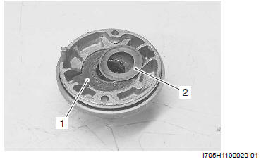
- Fit the washer (1) to the housing end with the tab aligned with the housing end cutaway, position the shim (2) and assemble the starter motor.
- Apply a small quantity of moly paste to the armature shaft.
 : Moly paste
99000-25140 (SUZUKI Moly paste or equivalent)
: Moly paste
99000-25140 (SUZUKI Moly paste or equivalent)
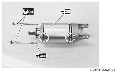
- Align the match mark on the starter motor case with the match mark on the housing end.
- Apply a small quantity of thread lock to the starter motor housing bolts and tighten them to the specified torque.
 : Thread lock cement
99000-32050 (Thread Lock Cement 1342 or equivalent)
: Thread lock cement
99000-32050 (Thread Lock Cement 1342 or equivalent)
Tightening torque
Starter motor housing bolt (a): 4 N*m (0.4 kgf-m, 3.0 lb-ft)
Starter Motor Inspection
Refer to "Starter Motor Disassembly and Assembly".
Carbon Brush
Inspect the carbon brushes for abnormal wear, cracks or smoothness in the brush holder.
If either carbon brush is defective, replace the brush holder set with a new one.
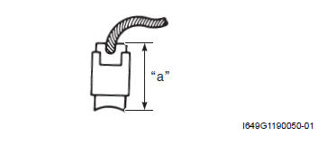
Measure the length "a" of the carbon brushes using a vernier calipers. If the measurement is less then the service limit, replace the brush holder set with a new one.
Brush length "a"
Service limit: 3.5 mm (0.14 in)
Special tool : 09900-20102 (Vernire calipers)
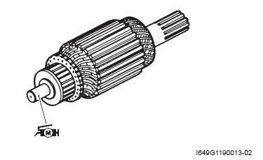
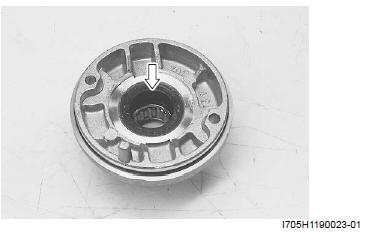
Commutator
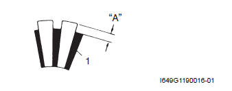
Inspect the commutator for discoloration, abnormal wear or undercut "A".
If the commutator is abnormally worn, replace the armature.
If the commutator surface is discolored, polish it with #400 sandpaper and wipe it using a clean dry cloth.
If there is no undercut, scrape out the insulator (1) with a saw blade.
Armature Coil
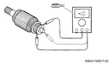
Measure for continuity between each segment. Measure for continuity between each segment and the armature shaft.
If there is no continuity between the segments or there is continuity between the segments and shaft, replace the armature with a new one.
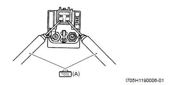
Special tool (A): 09900-25008 (Multi-circuit tester set)
Tester knob indication
Continuity set ( )
)
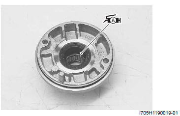
Bearing
Check the bearing of housing end for damage.
If any damage is found, replace the housing end.
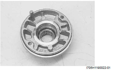
Oil Seal
Check the seal lip for damage.
If any damage is found, replace the housing end (Inside).
Starter Relay Removal and Installation
Refer to "Electrical Components Location".
Removal
1) Remove the upper meter panel. Refer to "Meter Panel Removal and Installation".
2) Disconnect the battery (-) lead wire from the battery.
Refer to "Battery Removal and Installation".
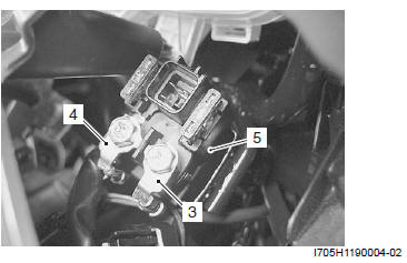
3) Disconnect the starter relay coupler (1) and remove the starter relay cover (2).
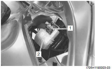
4) Disconnect the starter motor lead wire (3), battery (+) lead wire (4).
5) Remove the starter relay (5).
Installation
Install the starter relay in the reverse order of removal.
Starter Relay Inspection
Inspect the starter relay in the following procedures:
1) Remove the starter relay. Refer to "Starter Relay Removal and Installation".
2) Apply 12 V to "A" and "B" terminals and check for continuity between the (+) and (-) terminals using the multi-circuit tester. If the starter relay clicks and continuity is found, the relay is ok.
! CAUTION Do not apply battery voltage to the starter relay for five seconds and more, since the relay coil may overheat and get damaged.
Special tool (A): 09900-25008 (Multi-circuit tester set)
Tester knob indication
Continuity test ( )
)
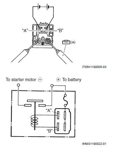
3) Measure the relay coil resistance between the terminals using the multi-circuit tester. If the resistance is not within the specified value, replace the starter relay with a new one.
Special tool (A): 09900-25008 (Multi-circuit tester set)
Starter relay resistance
3 - 6 Ω
4) Install the starter relay. Refer to "Starter Relay Removal and Installation".
See also:
 Suzuki Burgman 400 - Service manual > Schematic and Routing Diagram
Starting System Diagram Component Location
Suzuki Burgman 400 - Service manual > Turn Signal / Side-stand Relay Removal and Installation
Refer to "Electrical Components Location". Removal 1) Remove the meter panel. Refer to "Meter Panel Removal and Installation". 2) Remove the turn signal/side-stand relay (1).


