 Yamaha XMAX YP125R - Service manual > Adjusting the valve clearance
The following procedure applies to all of the valves.
TIP
- Valve clearance adjustment should be made on a cold engine, at room temperature.
- When the valve clearance is to be measured or adjusted, the piston must be at top dead center (TDC) on the compression stroke.
1. Remove:
- Storage box
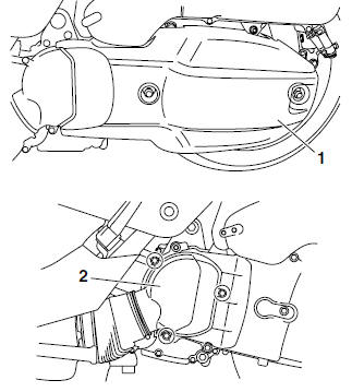
2. Remove:
- V-belt case cover "1"
- V-belt case air duct "2"
- V-belt case air filter element
3. Remove:
- Spark plug cap
- Spark plug "1"
- Cylinder head cover "2"
4. Remove:
- Timing mark accessing plug "1"
5. Measure:
- Valve clearance
Out of specification → Adjust.
 Valve clearance
(cold)
Valve clearance
(cold)
Intake 0.10-0.14 mm (0.0039-0.0055 in)
Exhaust 0.22-0.26 mm (0.0087-0.0102 in)
a. Turn the primary sheave nut on the left side of the crankshaft counterclockwise to turn the crankshaft.
b. Align the "I" mark "a" on the generator rotor with the stationary pointer "b" on the generator cover.
c. Check that the cam lobes are positioned as shown in the illustration.
d. Measure the valve clearance with a thickness gauge "1".
Out of specification → Adjust.
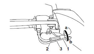
6. Adjust:
- Valve clearance
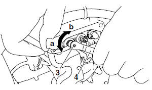
a. Loosen the locknut "1".
b. Insert a thickness gauge "2" between the end of the adjusting screw and the valve tip.
c. Turn the adjusting screw "3" in direction "a" or "b" with the tappet adjusting tool "4" until the specified valve clearance is obtained.
Direction "a" Valve clearance is increased.
Direction "b" Valve clearance is decreased.
 Tappet adjusting
tool
90890-01311
Tappet adjusting
tool
90890-01311
Six piece tappet set YM-A5970
d. Hold the adjusting screw to prevent it from moving and tighten the locknut to specification.
 Locknut (valve
clearance adjusting
screw)
Locknut (valve
clearance adjusting
screw)
7 Nm (0.7 m*kgf, 5.1 ft*lbf)
e. Measure the valve clearance again.
f. If the valve clearance is still out of specification, repeat all of the valve clearance adjustment steps until the specified clearance is obtained.
7. Install:
- Timing mark accessing plug
(along with the O-ring
 )
) - Cylinder head cover gasket

- Cylinder head cover
- Spark plug
- Spark plug cap
 Timing mark
accessing plug
8 Nm (0.8 m*kgf, 5.8 ft*lbf)
Timing mark
accessing plug
8 Nm (0.8 m*kgf, 5.8 ft*lbf)
Cylinder head cover bolt 10 Nm (1.0 m*kgf, 7.2 ft*lbf)
Spark plug 13 Nm (1.3 m*kgf, 9.4 ft*lbf)
8. Install:
- V-belt case air filter element
- V-belt case air duct
- V-belt case cover
 V-belt case air
duct bolt
7 Nm (0.7 m*kgf, 5.1 ft*lbf)
V-belt case air
duct bolt
7 Nm (0.7 m*kgf, 5.1 ft*lbf)
V-belt case cover bolt 7 Nm (0.7 m*kgf, 5.1 ft*lbf)
9. Install:
- Storage box
Adjusting the exhaust gas volume
TIP
Be sure to set the CO density level to standard, and then adjust the exhaust gas volume.
1. Remove:
- Upper panel
2. Set the main switch to "OFF".
3. Disconnect:
- Self-diagnosis signal coupler
4. Connect:
- FI diagnostic tool "1"
 FI diagnostic
tool 90890-03182
FI diagnostic
tool 90890-03182
5. While pressing the "MODE" button "1", set the main switch to "ON".
TIP
- "DIAG" appears on the LCD "2" of the FI diagnostic tool.
- "POWER" LED (Green) "3" comes on.
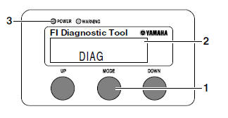
6. Press the "UP" button to select the CO adjustment mode "CO" or the diagnostic mode "DIAG".
7. After selecting "CO", press the "MODE" button.
8. Check that "C1" appears on the LCD of the FI diagnostic tool, and then press the "MODE" button.
9. Start the engine.
NOTICE
Perform the adjustment after the battery has been sufficiently charged.
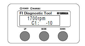
10.Change the CO adjustment volume by pressing the "UP" and "DOWN" buttons.
TIP
The CO adjustment volume and engine idling speed appears on the LCD of the FI diagnostic tool.
- To decrease the CO adjustment volume, press the "DOWN" button.
- To increase the CO adjustment volume, press the "UP" button.
11.Release the "DOWN" and "UP" buttons to execute the selection.
12.Set the main switch to "OFF" to cancel the mode.
13.Disconnect:
- FI diagnostic tool
14.Connect:
- Self-diagnosis signal coupler
15.Install:
- Upper panel
Adjusting the throttle cable free play
1. Check:
- Throttle cable free play "a"
Out of specification → Adjust.
 Throttle cable free play
3.0-5.0 mm (0.12-0.20 in)
Throttle cable free play
3.0-5.0 mm (0.12-0.20 in)
2. Adjust:
- Throttle cable free play
a. Slide back the rubber cover "1".
b. Loosen the locknut "2".
c. Turn the adjusting nut "3" in direction "a" or "b" until the specified throttle cable free play is obtained.
Direction "a" Throttle cable free play is increased.
Direction "b" Throttle cable free play is decreased.
d. Tighten the locknut.
e. Slide the rubber cover to its original position.
WARNING
After adjusting the throttle cable free play, start the engine and turn the handlebar to the right and to the left to ensure that this does not cause the engine idling speed to change.
Checking the spark plug
1. Disconnect:
- Spark plug cap "1"
2. Remove:
- Spark plug
NOTICE
Before removing the spark plug, blow away any dirt accumulated in the spark plug well with compressed air to prevent it from falling into the cylinder.
3. Check:
- Spark plug type
Incorrect → Change.
 Manufacturer/model
NGK/CPR9EA-9
Manufacturer/model
NGK/CPR9EA-9
4. Check:
- Electrode "1"
Damage/wear → Replace the spark plug.
- Insulator "2"
Abnormal color → Replace the spark plug.
Normal color is medium-to-light tan.
5. Clean:
- Spark plug (with a spark plug cleaner or wire brush)
6. Measure:
- Spark plug gap "a"
(with a wire thickness gauge) Out of specification → Regap.
 Spark plug gap
0.8-0.9 mm (0.031-0.035 in)
Spark plug gap
0.8-0.9 mm (0.031-0.035 in)
7. Install:
- Spark plug
 Spark plug
13 Nm (1.3 m*kgf, 9.4 ft*lbf)
Spark plug
13 Nm (1.3 m*kgf, 9.4 ft*lbf)
TIP
Before installing the spark plug, clean the spark plug and gasket surface.
8. Connect:
- Spark plug cap
Checking the ignition timing
TIP
Prior to checking the ignition timing, check the wiring connections of the entire ignition system.
Make sure that all connections are tight and free of corrosion.
1. Stand the vehicle on a level surface.
TIP
Place the vehicle on the centerstand.
2. Remove:
- Timing mark accessing plug "1"
3. Connect:
- Timing light "1" (onto the spark plug lead)
 Timing light
90890-03141
Timing light
90890-03141
Inductive clamp timing light YU-03141
4. Check:
- Ignition timing
a. Start the engine, warm it up for several minutes, and then let it run at the specified engine idling speed.
 Engine idling speed
1600-1800 r/min
Engine idling speed
1600-1800 r/min
b. Check that the stationary pointer "a" on the generator cover is within the firing range "b" on the generator rotor.
Incorrect firing range → Check the ignition system.
TIP
The ignition timing is not adjustable.
5. Disconnect:
- Timing light
6. Install:
- Timing mark accessing plug
(along with the O-ring  )
)
 Timing mark accessing plug
8 Nm (0.8 m*kgf, 5.8 ft*lbf)
Timing mark accessing plug
8 Nm (0.8 m*kgf, 5.8 ft*lbf)
See also:
 Yamaha XMAX YP125R - Service manual > Measuring the compression pressure
TIP Insufficient compression pressure will result in a loss of performance. 1. Remove: Storage box 2. Measure: Valve clearance


