 Suzuki Burgman 400 - Service manual > Center Leg Cover Removal and Installation
Removal
1) Remove the front frame cover. Refer to "Front Frame Cover Removal and Installation ".
2) Remove the left and right center leg cover (1).
! CAUTION Do not attempt to disconnect the ambient temperature sensor coupler.
Installation
Install the center leg cover in the reverse order of removal.
Front Box Removal and Installation
Removal
1) Remove the lower leg shield and front frame cover.
Refer to "Lower Leg Shield Removal and Installation" and "Front Frame Cover Removal and Installation".
2) Remove the ambient temperature sensor (1) from the front box.
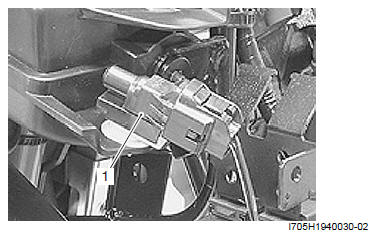
3) Remove the ECM (2) from the front box.
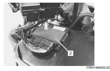
4) Remove the front box inner cover (3) and disconnect the power terminal coupler (4).
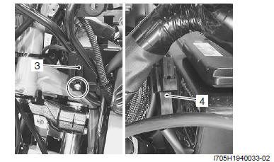
5) Remove the front box (5) by removing the screws and bolts.
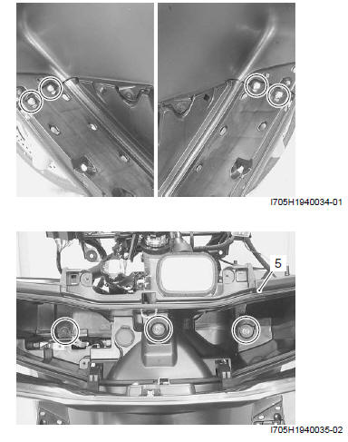
Installation
Install the front box in the reverse order of removal.
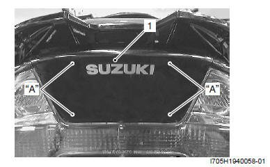
Pillion Rider Handle Cover Removal and Installation
Removal
Open the seat and remove the pillion rider handle cover (1).
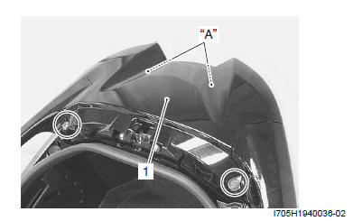
- Hooked point
Installation
Install the pillion rider handle cover in the reverse order of removal.
Pillion Rider Handle Removal and Installation
Removal
1) Remove the pillion rider handle cover. Refer to "Pillion Rider Handle Cover Removal and Installation".
2) Remove the pillion rider handle (1).
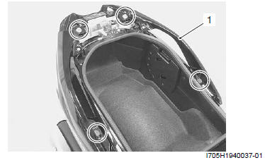
Installation
Install the pillion rider handle in the reverse order of removal.
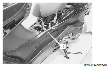
Center Frame Cover Removal and Installation
Removal
Pull out the center frame cover (1).
- Hooked point
Installation
Install the center frame cover in the reverse order of removal.
See also:
 Suzuki Burgman 400 - Service manual > Side Leg Shield Removal and Installation
Removal 1) Remove the left and right rear floor mats (1), fasteners and screws.
Suzuki Burgman 400 - Service manual > Lower Frame Cover Removal and Installation
Removal Pull out the lower frame cover (1). Installation Push in the lower frame cover (1). Hooked point


