 Suzuki Burgman 400 - Service manual > Clutch Shoe / Movable Driven Face Components
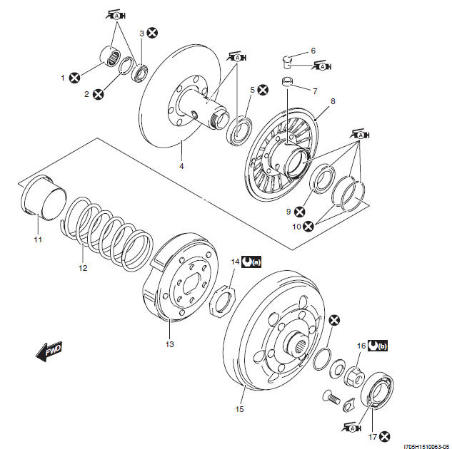
- Needle bearing
- Snap ring
- Bearing
- Fixed driven face
- Oil seal
- Movable driven pin
- Movable driven pin spacer
- Movable driven face
- Oil seal
- O-ring
- Movable driven face seat
- Movable driven face spring
- Clutch shoe assembly
- Clutch shoe nut
- Clutch housing
- Clutch housing nut
- Inner clutch cover bearing
- : 105 N*m (10.5 kgf-m, 76.0 lb-ft)
- : 85 N*m (8.5 kgf-m, 61.5 lb-ft)
 : Apply grease.
 : Do not reuse.
Clutch Shoe / Movable Driven Face Disassembly and Assembly
Refer to "V-belt Type Continuously Variable Automatic Transmission Removal and Installation" and "Movable Drive Face Component".
Disassembly
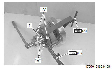
1) Engage the "A" of the special tool with five holes on the clutch shoe and fix the clutch shoe/movable driven face assembly by turning in the special tool handle.
2) Remove the clutch shoe nut (1).
Special tool
(A): 09922-31440 (Clutch spring compressor)
(B): 09920-31020 (Extension handle)
! CAUTION Since a high spring force applies to the clutch shoe assembly, care must be used so as not to cause the clutch shoe assembly and movable driven face to come off abruptly.
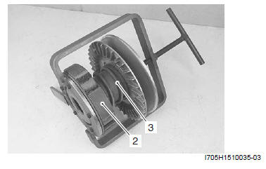
3) Remove the clutch shoe plate (2) and spring (3) by loosening the special tool handle slowly.
! CAUTION The clutch shoe cannot be disassembled.
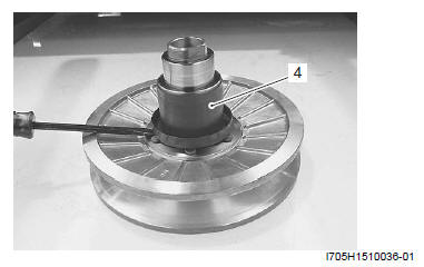
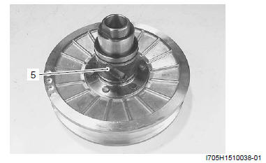
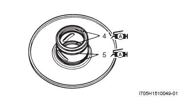
4) Remove the movable driven face seat (4) using a sharp point such as flat screwdriver.
5) Remove the movable driven pins (5) (3 pcs).
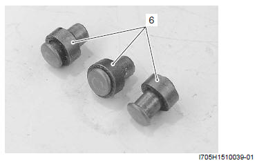
6) Remove the movable driven pin spacers (6).
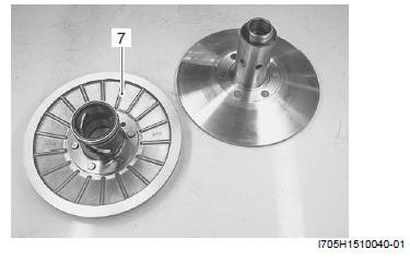
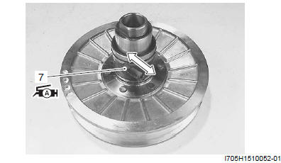
7) Remove the movable driven face (7).
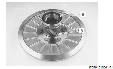
8) Remove the O-ring (8) and oil seal (9).
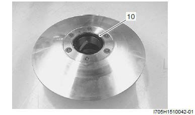
9) Remove the oil seal (10).
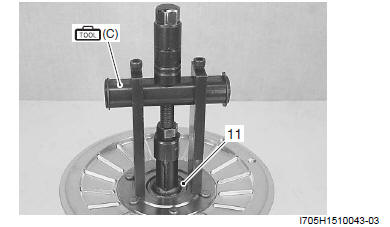
10) Remove the needle bearing (11) using the special tool.
Special tool (C): 09921-20240 (Bearing remover set)
11) Remove the snap ring.
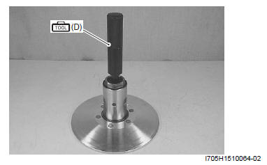
12) Remove the bearing using the special tool.
Special tool (D): 09913-70210 (Bearing installer set)
Assembly
Refer to "Clutch Shoe and Movable Driven Face Parts Inspection".
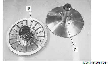
1) Install the bearing (1) to the fixed driven face (2) using a spacer, the size being appropriate for outside diameter of the bearing.
! CAUTION Use a new bearing.
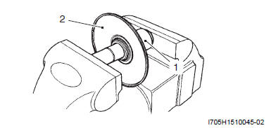
2) Install the snap ring.
! CAUTION Use a new snap ring.
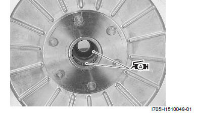
3) Install needle bearing (3) using a spacer, the size being appropriate for the outside diameter of the bearing.
! CAUTION
- Use a new bearing.
- The stamp mark on the needle bearing should face outside when installed.
4) Apply the grease both to the bearing and needle bearing.
! CAUTION Fill sufficient grease in the grease groove inside the fixed driven face and also on the needle bearing.
: Grease
99000-25010 (SUZUKI SUPER GREASE A or equivalent)
5) Install the oil seal (4) and O-ring (5) to the movable driven face.
! CAUTION Use a new oil seal and O-ring.
6) Apply the grease both to the lip of oil seal and O-ring.
: Grease
99000-25010 (SUZUKI SUPER GREASE A or equivalent)
7) Apply the grease in the grease groove of movable driven face (6) and sliding face.
: Grease
99000-25010 (SUZUKI SUPER GREASE A or equivalent)
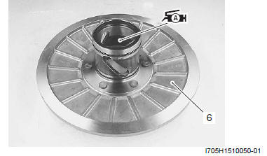
8) Assemble the movable driven face (6) to the fixed driven face (2).
9) Install the movable driven pin (7) to the pin hole with the grease lightly coated.
: Grease 99000-25010
(SUZUKI SUPER GREASE A or equivalent)
10) Check that the movable driven face can move smoothly.
11) Install the movable driven face seat (8).
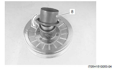
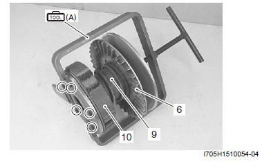
12) Install the spring (9) and clutch shoe assembly (10) to the movable driven face (6) and attach the special tool.
13) Engage the pawl of special tool to the hole of the clutch shoe plate.
Special tool (A): 09922-31440 (Clutch spring compressor)
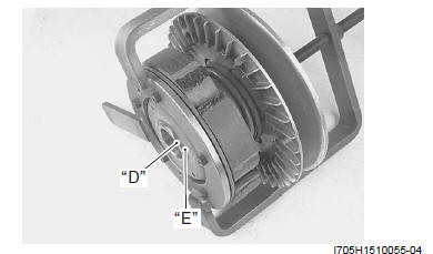
14) While the special tool handle is being turned in slowly, engage two flats "D" on the end of movable driven face with the same shaped hole "E" on the clutch shoe plate.
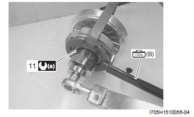
15) Check that the pawl on the special tool is securely fitted into the hole on the clutch shoe plate and tighten the clutch shoe nut (11) to the specified torque.
Special tool (B): 09920-31020 (Extension handle)
Tightening torque
Clutch shoe nut (a): 105 N*m (10.5 kgf-m, 76.0 lb-ft)
See also:
 Suzuki Burgman 400 - Service manual > Movable Face
Refer to "Movable Drive Face Disassembly and Assembly". Inspect the following parts. Inspect the movable face for any stepped wear on the drive face. If any defects are found, replace the drive face with a new one.
Suzuki Burgman 400 - Service manual > Clutch Shoe and Movable Driven Face Parts Inspection
Refer to "Clutch Shoe / Movable Driven Face Disassembly and Assembly ". Inspect the following parts. Clutch Housing Inspection Check for the following items and if any defects are found, replace it with a new one. Existence of abnormal scratch. Measurement of clutch housing inside diameter.


