 Suzuki Burgman 400 - Service manual > Heated Oxygen Sensor (HO2S) Removal and Installation
Removal
! WARNING Do not remove the HO2 sensor while it is hot.
! CAUTION
- Be careful not to expose the HO2 sensor to excessive shock.
- Do not use an impact wrench when removing or installing the HO2 sensor.
- Be careful not to twist or damage the sensor lead wires.
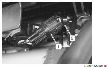
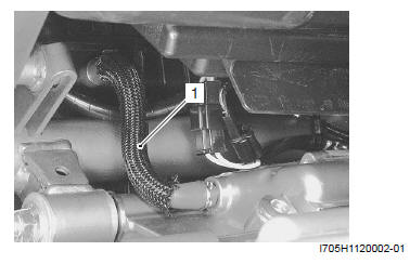
1) Disconnect the HO2 sensor coupler (1) and remove the clamp (2).
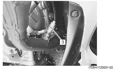
2) Remove the HO2 sensor (3).
Installation
! CAUTION Do not apply oil or other materials to the sensor air holes.
Install the HO2 sensor in the reverse order of removal.
Pay attention to the following point:
- Tighten the HO2 sensor to the specified torque.
Tightening torque
HO2 sensor: 48 N*m (4.8 kgf-m, 34.5 lb-ft)
Heated Oxygen Sensor (HO2S) Inspection
Inspect the HO2 sensor in the following procedures:
1) Inspect the HO2 sensor and its circuit referring to flow table of the malfunction code (C44). Refer to "DTC "C44" (P0130, P0135): HO2 Sensor (HO2S) Circuit Malfunction".
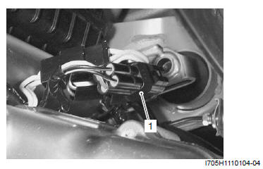
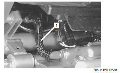
2) Disconnect the HO2 sensor coupler (1).
NOTE
- Temperature of the sensor affects resistance value largely.
- Make sure that the sensor heater is at correct temperature.
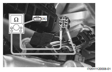
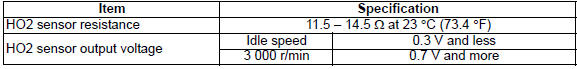
3) Check the resistance between the terminals (W - W) of the HO2 sensor. If the resistance is not within the standard range, replace the HO2 sensor with a new one.
Resistance
Approx. 11.5 - 14.5 Ω (at 23 ºC)
Special tool (A): 09900-25008 (Multi-circuit tester set)
Tester knob indication
Resistance (Ω)
4) Connect the HO2 sensor coupler securely.
! CAUTION Do not apply oil or other materials to the sensor air hole.
PCV Hose Inspection
Inspect the PCV hose (1) for wear and damage.
If it is worn or damaged, replace the PCV hose with a new one.
Check that the PCV hose (1) is securely connected.
PCV Hose Removal and Installation
Removal
1) Remove the PCV hose (1).
Installation
Install the PCV hose in the reverse order of removal.
Specifications
Service Data
FI Sensors
Electrical
Unit: mm (in)

Tightening Torque Specifications

Reference: For the tightening torque of fastener not specified in this section, refer to "Tightening Torque Specifications".
Special Tools and Equipment
Special Tool
 09900-25008
Multi-circuit tester set
09900-25008
Multi-circuit tester set
See also:
 Suzuki Burgman 400 - Service manual > Fuel Injection System Description
Precautions Precautions for Emission Control Devices Refer to "General Precautions. General Description
Suzuki Burgman 400 - Service manual > Engine Electrical Devices
Precautions Precautions for Engine Electrical Device Refer to "General Precautions" and "Precautions for Electrical Circuit Service".


