 Suzuki Burgman 400 - Service manual > Repair Instructions
Brake Light Switch Inspection
Front Brake Light Switch
Inspect the front brake light switch in the following procedures:
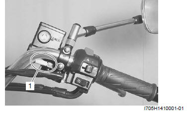
1) Remove the handlebar cover. Refer to "Handlebar Cover Removal and Installation".
2) Disconnect the front brake light switch lead wire couplers (1).
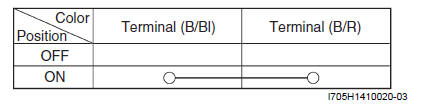
3) Inspect the switch for continuity with a tester.
If any defects are found, replace the front brake light switch with a new one. Refer to "Front Master Cylinder / Brake Lever Disassembly and Assembly".
Special tool : 09900-25008 (Multi-circuit tester set)
Tester knob indication
Continuity ( )
)
Front brake light switch
4) Connect the front brake light switch lead wire couplers.
Rear Brake Light Switch
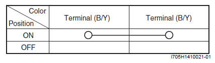
Inspect the rear brake light switch in the same manner as the front brake light switch. Refer to "Brake Light Switch Inspection".
Rear brake light switch
Brake Fluid Level Check
Refer to "Brake System Inspection ".
Brake Hose Inspection
Refer to "Brake System Inspection".
Air Bleeding from Brake Fluid Circuit
Air trapped in the brake fluid circuit acts like a cushion to absorb a large proportion of the pressure developed by the master cylinder and thus interferes with the full braking performance of the brake caliper. The presence of air is indicated by "sponginess" of the brake lever and also by lack of braking force. Considering the danger to which such trapped air exposes the machine and rider, it is essential that after remounting the brake and restoring the brake system to the normal condition, the brake fluid circuit be purged of air in the following manner:
! CAUTION Handle brake fluid with care: the fluid reacts chemically with paint, plastic, rubber materials, etc.
Front Brake
1) Fill the master cylinder reservoir to the top of the inspection window. Place the reservoir cap to prevent dirt from entering.
2) Attach a hose to the air bleeder valve, and insert the free end of the hose into a receptacle.
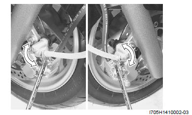
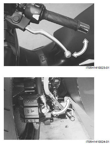
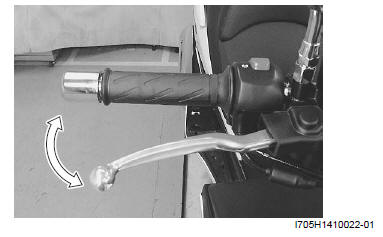
3) Squeeze and release the brake lever several times in rapid succession and squeeze the lever fully without releasing it.
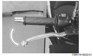
4) Loosen the air bleeder valve by turning it a quarter of a turn so that the brake fluid runs into the receptacle, this will remove the tension of the brake lever causing it to touch the handlebar grip.
5) Close the air bleeder valve, pump and squeeze the lever, and open the valve.
6) Repeat this process until the fluid flowing into the receptacle no longer contains air bubbles.
NOTE While bleeding the brake system, replenish the brake fluid in the reservoir as necessary.
Make sure that there is always some fluid visible in the reservoir.
7) Close the air bleeder valve and disconnect the hose.
8) Fill the reservoir with brake fluid to the top of the inspection window.
Tightening torque
Air bleeder valve (Front brake): 6.0 N*m (0.6 kgf-m, 4.5 lb-ft)
9) Install the reservoir cap.
Rear Brake
Bleed air from the rear brake in the same manner as the front brake.
Tightening torque
Air bleeder valve (Rear brake): 6.0 N*m (0.6 kgf-m, 4.5 lb-ft)
Brake Fluid Replacement
! CAUTION Handle brake fluid with care: the fluid reacts chemically with paint, plastic, rubber materials, etc.
Front Brake
1) Place the motorcycle on a level surface and keep the handlebars straight.
2) Remove the brake fluid reservoir cap and diaphragm.
3) Suck up the old brake fluid as much as possible.
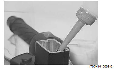
4) Fill the reservoir with new brake fluid.
BF: Brake fluid (DOT 4)
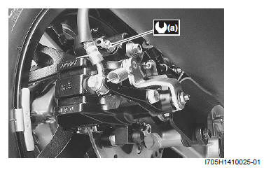
5) Connect a clear hose to the air bleeder valve and insert the other end of the hose into a receptacle.
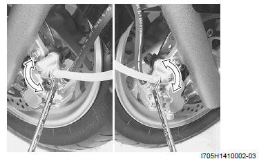
6) Loosen the air bleeder valve and pump the brake lever until the old brake fluid flows out of the brake system.
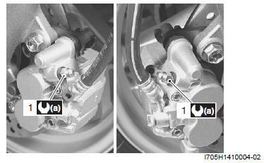
7) Close the air bleeder valve (1) and disconnect the clear hose.
Tightening torque
Air bleeder valve (Front brake) (a): 6.0 N*m (0.6 kgf-m, 4.5 lb-ft)
8) Fill the reservoir with new brake fluid to the upper line of the reservoir.
Rear brake
Brake fluid replacement in the same manner as the front brake.
Tightening torque
Air bleeder valve (Rear brake) (a): 6.0 N*m (0.6 kgf-m, 4.5 lb-ft)
See also:
 Suzuki Burgman 400 - Service manual > Brake Fluid Information
! WARNING This brake system is filled with an ethylene glycol-based DOT 4 brake fluid. Do not use or mix different types of fluid, such as silicone-based or petroleum-based. Do not use any brake fluid taken from old, used or unsealed containers. Never reuse brake fluid left over from the last servicing or which has been stored for long periods of time. When storing brake fluid, seal the container completely and keep it away from children. When replenishing brake fluid, take care not to get dust into the fluid. When washing brake components, use new brake fluid. Never use cleaning solvent. A contaminated brake disc or brake pad reduces braking performance. Discard contaminated pads and clean the disc with high quality brake cleaner or neutral detergent.
Suzuki Burgman 400 - Service manual > Front Brake Hose Removal and Installation
Removal 1) Remove the front leg shield. Refer to "Front Leg Shield Removal and Installation". 2) Drain brake fluid. Refer to "Brake Fluid Replacement".


