 Suzuki Burgman 400 - Service manual > Repair Instructions
Exterior Parts Components
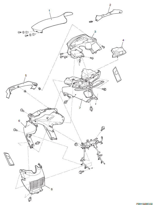
- Wind screen
- Upper meter panel
- Meter panel assembly
- Front panel
- Front leg shield cover
- Front leg shield
- Front box assembly
- Lower leg shield
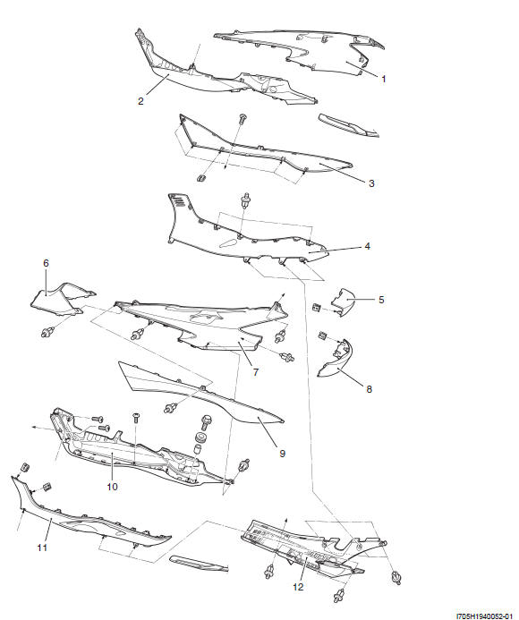
- Frame cover (RH)
- Footboard (RH)
- Center leg cover (RH)
- Side leg shield (RH)
- Center frame cover
- Front frame cover
- Frame cover (LH)
- Lower frame cover
- Center leg cover
- Footboard (LH)
- Side leg shield (LH)
- Under cover
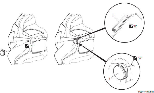
- Front reflex reflector (For E-03, 28, 33)
- Adhere the front reflex reflector on to the front leg shield.
- Set the reflector to the edge of front leg shield.
- Align the projection of reflector with the joint part of meter panel and front box.
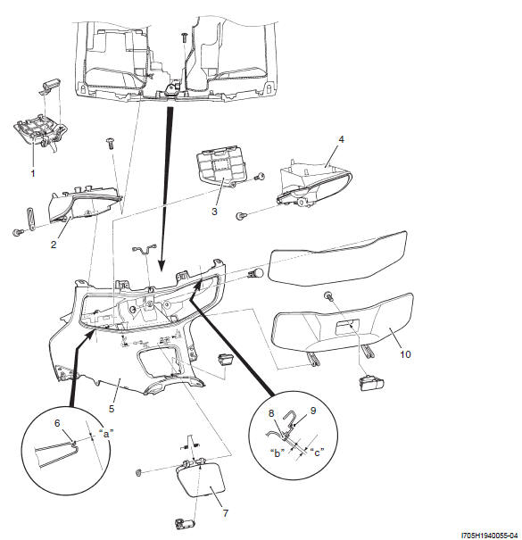
- Fuel lid
- Front box inner cover (LH)
- Battery cover
- Front box inner cover (RH)
- Front box
- Cushion
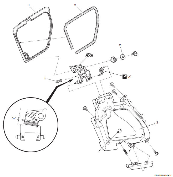
- Fuel lid
- Inner cushion
- Cushion
- Front box lid
- 0 mm
- 0 - 3 mm (0 - 0.12 in)
- 4 mm (0.16 in)
- Front panel box lid
- Cushion
- Front panel box
- 2 mm (0.08 in)
- Do not exchange the right one and left one.
 : Apply silicone
grease.
: Apply silicone
grease.
- Pillion rider handle
- Pillion rider handle cover
- To frame
- Seat molding
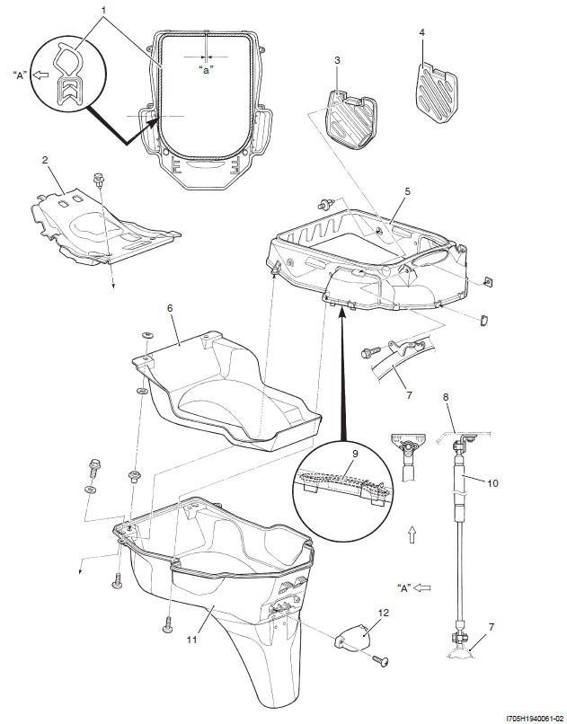
- Helmet box front cover
- Helmet box lid (LH)
- Helmet box lid (RH)
- Upper helmet box
- Mat
- Frame
- Seat
- Tool band
- Seat damper
- Lower helmet box
- License plate light cover
- 0 - 1 mm (0 - 0.04 in)
- Outside
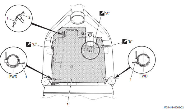
- Fuel tray mudguard sheet
- Frame
- The seat must be assembled behind the horn.
- Face the clamp locking part inside and clamp end backward.
- Clamp the seat with the wiring harness.
Inner Cover Construction
- Inner cover
- Clamp
: Clamp ends should face inside. The clamps are not fastened too much.
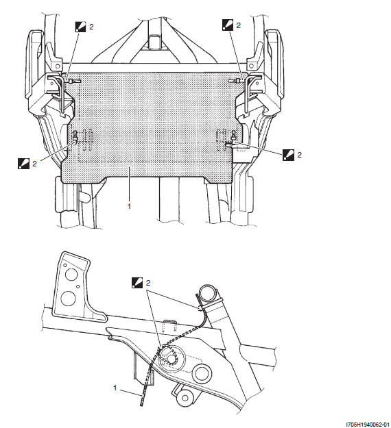
Seat Lock Cable Removal and Installation
Refer to "Seat Lock Cable Routing Diagram".
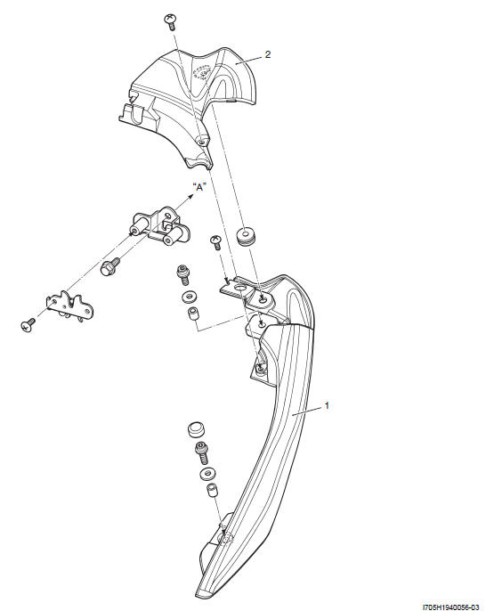
Handlebar Cover Removal and Installation
Removal
1) Remove the rear handlebar cover (1).
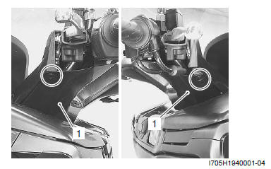
2) Remove the front handlebar cover (2).
Installation
Install the handlebar covers in the reverse order of removal.
See also:
 Suzuki Burgman 400 - Service manual > Schematic and Routing Diagram
Seat Lock Cable Routing Diagram Seat lock cable No. 1 Seat lock cable No. 2 Brake-lock cable Starter motor lead wire Clamp : Clamp the brake-lock cable, starter motor lead wire and seat lock cable. Seat lock cable Pass the seat lock cable No. 2 through front of the seat lock cable No. 1. Pass the seat lock cable No. 1 through inside of the frame. Pass the cables through inner side of the frame. Pass the cables through bottom and inner side of the frame. Seat lock cable set position Change set position only when seat locking or releasing is impossible.
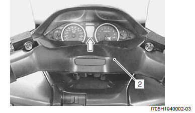
Suzuki Burgman 400 - Service manual > Upper Meter Panel Removal and Installation
Removal Pull out the upper meter panel (1). Hooked point


